Cleaning device

Active Publication Date: 2007-01-25
AVET
View PDF4 Cites 35 Cited by
  • Summary
  • Abstract
  • Description
  • Claims
  • Application Information

AI Technical Summary

Benefits of technology

[0012] It is an object of the invention to provide a fluid flow assembly for enhancement of reliability of continuous fluid flow in a non-gravity feed cleaning device.
[0013] It is another object to provide a fluid flow assembly of the above type having improved fluid integrity between a cleaning fluid storage bottle and downstream elements of th

Problems solved by technology

A problem with such known cleaning devices, however, is the sealing tightness of the coupling piece with the coupling counter-piece, with the result that a risk arises of cleaning agent passing unintentionally into the fluid coupling and retaining cylinder and contaminating it, as well as the fact that the cleanirig material is consequently discharged with

Method used


Image

  • Cleaning device
  • Cleaning device
  • Cleaning device

Examples


Embodiment Construction

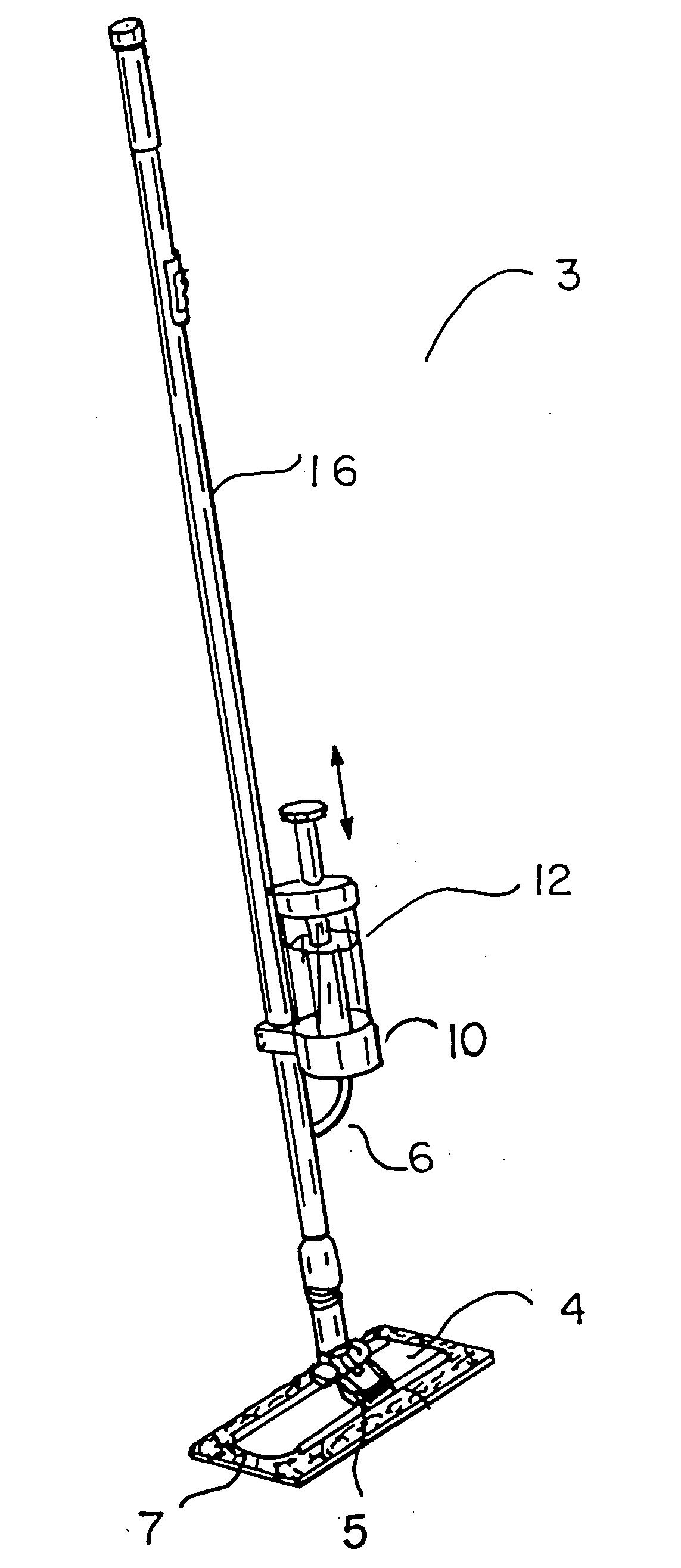
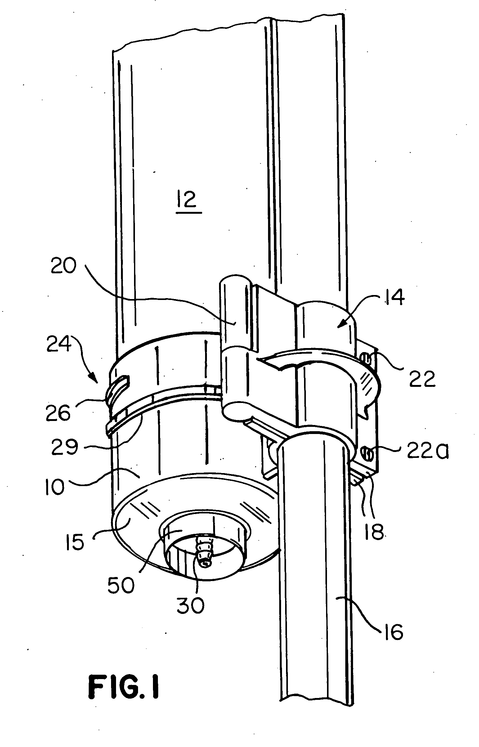
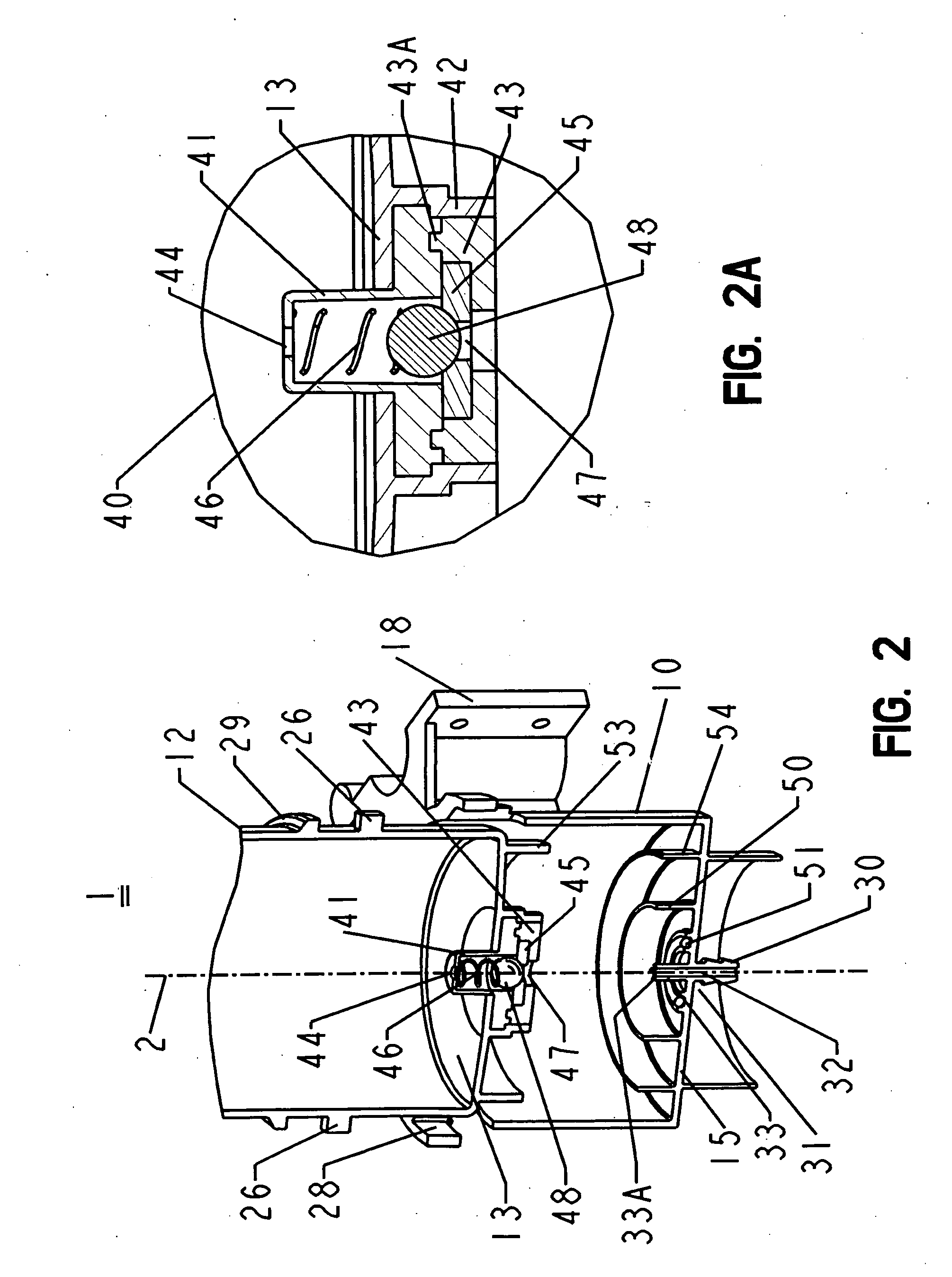
[0026] Cleaning devices of many types (not shown in the drawings) including, particularly, one with which the inventive cleaning fluid flow assembly is intended to be used. Fluid flow assembly 1 includes a storage container 12 for holding a cleaning fluid and a fluid coupling and retaining cylinder 10 to which storage container 12 is connected (see FIGS. 1-4). The cylinder 10 utilizes a securing collar 14 for the retention of cylinder 10 to a handling rod 16 of the overall cleaning device (not shown). Securing collar 14 includes two clamping elements 18, connected to each other by hinge 20 at one side and screws 22 / 22a at the other, the cooperative effect of which is to facilitate the selectable securement and removal of cylinder 10 from rod 16.

[0027] In accordance with the present invention, storage container 12 is connected in a releasable manner to cylinder 10 using a bayonet fitting 24 in which bayonet projections 26 at opposite sides of the container are provided integrally th...


PUM

PropertyMeasurementUnit
Flow rateaaaaaaaaaa
Distanceaaaaaaaaaa

Abstract

A fluid flow assembly includes a storage container connected to a fluid coupling and retaining cylinder. The connection is secured by a bayonet connection and walls between the bases of the container and cylinder. The storage container has a ball valve assembly disposed at its base, which includes an upper housing, a lower extension, and a ball valve axially disposed therein. The cylinder includes an axial hollow elongate fluid outlet on the base, co-axially aligned with an outlet port of the ball valve assembly of the container. The upper portion of the fluid outlet is a male coupling, which penetrates into the outlet port, when the container is connected to the cylinder, and axially displaces a valve ball from its closed position into an open position, enabling fluid flowing thru the ball valve assembly of the storage container, into the hollow fluid outlet of the cylinder, and downstream of it.

Description

CROSS REFERENCE TO RELATED APPLICATION [0001] This application is a Continuation-In-Part of PCT patent application No. PCT / EP2005 / 004914 filed May 6, 2005, which claims the priority of German Utility Model No. 20 2004 019 888.6 filed Dec. 20, 2004, which are hereby incorporated by reference in their entirety.BACKGROUND OF THE INVENTION [0002] The invention relates to a fluid flow assembly and bottle for a cleaning device with a storage container for cleaning fluid, which can be secured in a detachable manner by means of a screw or bayonet connection to a fluid coupling and retaining cylinder with a fluid line which runs from the storage container to a fluid outlet, and with a female line coupling which has a coupling piece arranged at the storage container and a male coupling counter-piece arranged at the fluid coupling and retaining cylinder, whereby the container base facing the fluid coupling and retaining cylinder is provided with a container sealing piece. [0003] A cleaning dev...

Claims


Application Information

Patent Timeline
IPC IPC(8): A47L13/22A46B11/00
CPCA46B11/00A47L13/22A46B11/0065
Inventor SACKS, ROLAND
Owner AVET
Why Eureka
Try Eureka