Cooled turbine blade or vane for a gas turbine, and use of a turbine blade or vane of this type

a technology of turbine blades and turbine blades, which is applied in the direction of machines/engines, mechanical equipment, liquid fuel engines, etc., can solve the problems of limited fatigue service life of the turbine blade as a whole, difficult cooling of wide platform overhangs, and increased fatigue service li

Inactive Publication Date: 2007-01-25
SIEMENS AG
View PDF2 Cites 73 Cited by
  • Summary
  • Abstract
  • Description
  • Claims
  • Application Information

AI Technical Summary

Benefits of technology

[0022] The abovementioned cooling concepts can be used particularly effectively in a turbine blade or vane in which the blade or vane root runs in the longitudinal direction of the blade profile, and the platform has two platform longitudinal edges bent parallel and running in the longitudinal direction, and in which the respective blade or vane root surface facing the suction-side and pressure-side profile walls is convexly and concavely curved in a corresponding way to the associated platform longitudinal edge. In a turbine blade or vane of this type with a curved blade or vane root an...

Problems solved by technology

The high stresses in the platform and in the transition region limit the fatigue service life of the turbine blade as a whole.
Moreover, particularly in the case of turbine blades with a high diverting action and accordingly a strong curvature the ...

Method used


Image

  • Cooled turbine blade or vane for a gas turbine, and use of a turbine blade or vane of this type
  • Cooled turbine blade or vane for a gas turbine, and use of a turbine blade or vane of this type
  • Cooled turbine blade or vane for a gas turbine, and use of a turbine blade or vane of this type

Examples


Embodiment Construction

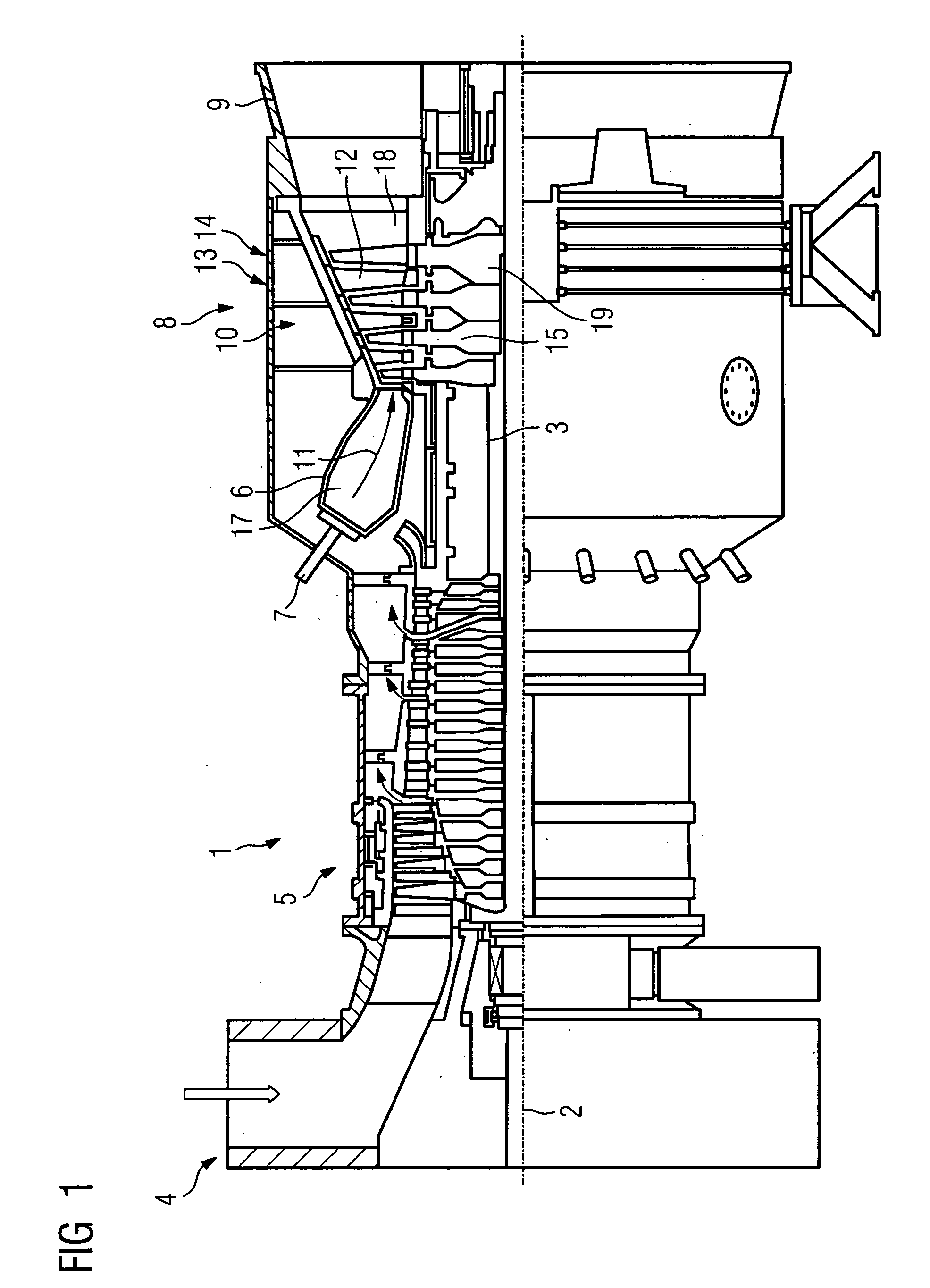
[0036]FIG. 1 shows a partial longitudinal section through a gas turbine 1. In its interior, it has a rotor 3 which is mounted such that it can rotate about an axis of rotation 2 and is also referred to as the turbine rotor. An intake casing 4, a compressor 5, a toric annular combustion chamber 6 with a plurality of burners 7 arranged rotationally symmetrically with respect to one another, a turbine unit 8 and an exhaust gas casing 9 follow one another along the rotor 3. The annular combustion chamber 6 forms a combustion space 17 which is in communication with an annular hot gas duct 18. There, four successive turbine stages 10 form the turbine unit 8. Each turbine stage 10 is formed from two blade or vane rings. As seen in the direction of flow of a hot gas 11 generated in the annular combustion chamber 6, a guide vane row 13 is in each case followed by a row 14 formed from rotor blades 15 in the hot gas duct 18. The guide vanes 12 are secured to the stator, whereas the rotor blade...


PUM


Abstract

The invention relates to a turbine blade or vane for a gas turbine, having a blade or vane root, which is successively adjoined by a platform region with a transversely running platform and then a blade or vane profile which is curved in the longitudinal direction, having a platform surface, which is provided at the platform and can be exposed to hot gas, and having at least one cavity, which is open on the root side, through which a coolant can flow and which extends through the blade or vane root and at least into the platform region and is surrounded by an inner wall, the contour of which, running in the platform region, is set back with respect to the contour running in the blade or vane root, so as to form a recess. To provide a turbine blade or vane which has a service life which is extended with respect to fatigue while at the same time saving cooling air, the invention proposes that the recess, as a partial cavity, is set back so deep into the platform that it lies opposite the platform surface, forming an at least partially hollow platform, and that there is at least one means for diverting the coolant into the partial cavity.

Description

CROSS REFERENCE TO RELATED APPLICATION [0001] This application claims the benefit of U.S. Provisional Patent Application Ser. No. 60 / 702,313, filed Jul. 25, 2005.FIELD OF THE INVENTION [0002] The invention relates to a turbine blade or vane for a gas turbine, having a blade or vane root, which is successively adjoined by a platform region with a transversely running platform and then a blade or vane profile which is curved in the longitudinal direction, having at least one cavity which is open on the root side, through which a coolant can flow and which extends through the blade or vane root and the platform region into the blade or vane profile. The invention also relates to the use of a turbine blade or vane of this type. BACKGROUND OF THE INVENTION [0003] EP 1 355 041 A2 has disclosed a turbine blade or vane of this type. The cast turbine blade has a cavity which extends from the blade root through the platform into the blade profile. The cross section of the cavity is substantia...

Claims


Application Information

Patent Timeline
IPC IPC(8): F01D11/00
CPCF01D5/147F01D5/186F01D5/187F05D2240/81F05D2230/21F05D2260/202F01D25/12
Inventor BEECK, ALEXANDER RALPHIRMISCH, STEFAN
Owner SIEMENS AG
Why Eureka
Try Eureka