
Three-prong retractor with elastomeric sheath

a retractor and elastomeric technology, applied in the field of retractors, can solve problems such as the sliding of surgical tools on the skin of patients, and achieve the effect of facilitating this rotation

Active Publication Date: 2007-01-25
STRYKER EURO OPERATIONS HLDG LLC
View PDF39 Cites 35 Cited by
  • Summary
  • Abstract
  • Description
  • Claims
  • Application Information

AI Technical Summary

Benefits of technology

[0007] In a preferred embodiment the present invention is a retractor comprising a first supporting member, a second supporting member coupled to said first supporting member for selective translational movement of said first and second supporting members towards and away from each other, a holding arm connected to said second supporting member on an axis, a medial blade attached to said first supporting member having a distal end remote from the first supporting member, and a pair of lateral blades attached to said holding arm, each of said lateral blades having a distal end remote from said holding arm, said holding arm facilitating movement of said ends toward and away from each other in a plane that intersects the direction of the translational movement of said first supporting member and said second supporting member. The holding arm preferably rotates such that the distal ends of the lateral blades rotate away from the medial blade. An actuator may facilitate this rotation.

Problems solved by technology

These retractors pose two problems: the opening created by the retractor is an elongated opening that is usually not large enough to accommodate a plurality of surgical tools, and there is no protection of the skin from the surgical area which may lead to the slippage of surgical tools on to the skin of the patient.

Method used


Image

  • Three-prong retractor with elastomeric sheath
  • Three-prong retractor with elastomeric sheath
  • Three-prong retractor with elastomeric sheath

Examples


Embodiment Construction

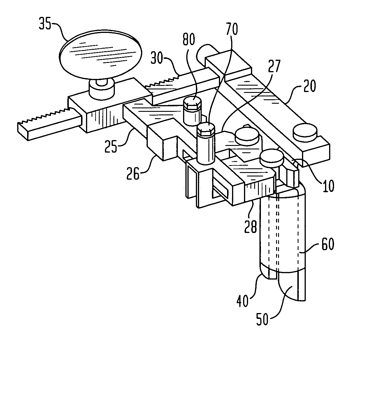
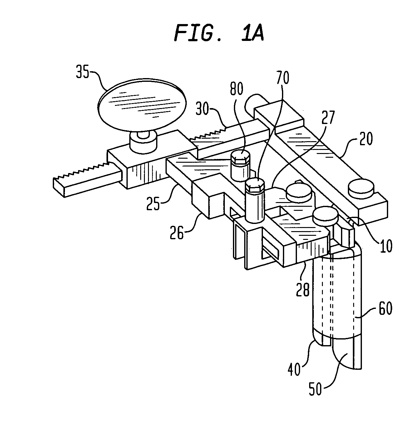
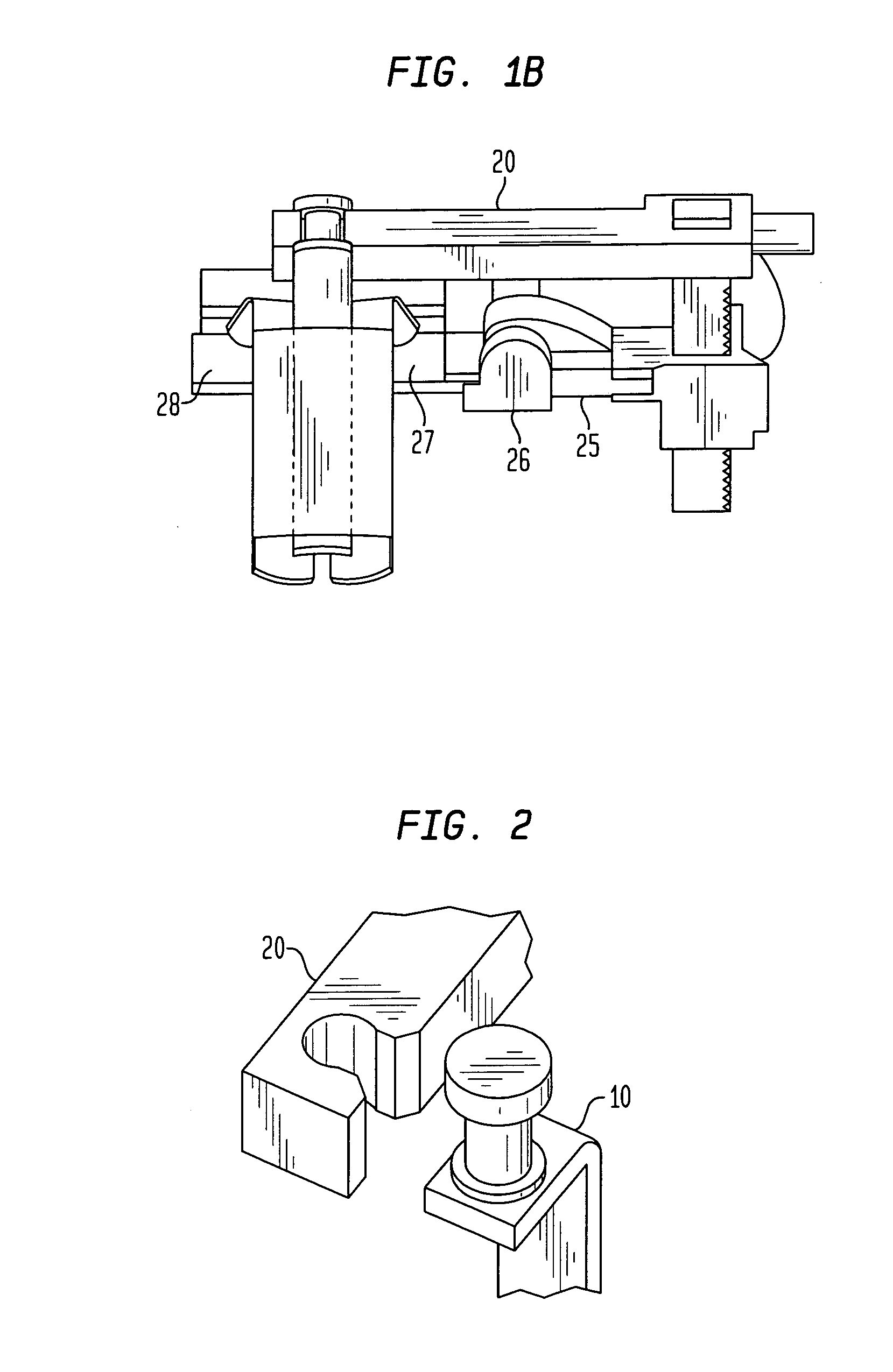
[0020]FIGS. 1A and 1B depict one embodiment of the versatile frame retractor according to the present invention in a closed position for insertion into an incision. The medial blade 10 is attached to a first supporting member 20, which is coupled to the second supporting member 25 with a rack member 30 and crank 35, or other expedient as known in the art. The second supporting member 25 is connected to the holding arm 26, which holds the first retaining member 27 and the second retaining member 28. The first lateral blade 40 and second lateral blade 50 are held by the first retaining member 27 and the second retaining member 28. The first lateral blade 40 and second lateral blade 50 are positioned against the medial blade 10 for ease of insertion of the retractor into a small incision. The medial blade 10 is preferably shorter than the lateral blades to better accommodate the anatomy of the spine; specifically the arch of the lamina and the greater depth of the transverse process. T...


PUM


Abstract

A three-prong retractor is disclosed which is inserted into an incision in a patient in order to create an area for surgery. The retractor opens such that two blades move away from a first blade to create an elongated opening. The two blades may then move away from each other in a direction that intersects the direction of the movement of the first blade away from the two blades. The ends of the two blades remote from the retractor body may then move away from the end of the first blade remote from the retractor body to further open the incision. The retractor may also have an elastomeric sheath surrounding the blades in order to create a barrier between the surgical area and the patient's skin.

Description

CROSS REFERENCE TO RELATED APPLICATIONS [0001] The present application claims benefit of U.S. Provisional Application No. 60 / 642,234, filed Jan. 7, 2005, the disclosure of which is hereby incorporated by reference herein.BACKGROUND OF THE INVENTION [0002] The present invention relates to a device used to retract the tissue of the body of a patient during surgery. More specifically, the present invention relates to a retractor that facilitates enlarging a surgical cavity and providing access to a surgical site. [0003] Invasive surgical procedures require a surgeon to create an incision in the patient's skin in order to access the area within the patient's body where the surgery must be performed. It is desirable for the surgeon to create a small incision because a smaller incision takes less time to heal and thus causes less trauma to the patient. The incision, however, must be large enough to accommodate the surgeon's tools necessary to perform the surgery. Thus, retractors are ofte...

Claims


Application Information

Patent Timeline
IPC IPC(8): A61B1/32
CPCA61B17/02A61B2019/481A61B17/0293A61B17/0206A61B2090/08021
Inventor MARTIN, GREGABDELGANY, MAHMOUD F.BUSH, WILLIAM
Owner STRYKER EURO OPERATIONS HLDG LLC
Learn More