Laparoscopic ultrasound robotic surgical system

a robotic surgical system and laser technology, applied in the field of robotic surgical systems, can solve the problems of inability to manually palpate hidden or solid organs, the difficulty of manipulating the ultrasound probe, and the considerable expertise of the ablation probe, so as to promote surgeon efficiency and facilitate us

Inactive Publication Date: 2007-01-25
THE JOHN HOPKINS UNIV SCHOOL OF MEDICINE +1
View PDF48 Cites 576 Cited by
  • Summary
  • Abstract
  • Description
  • Claims
  • Application Information

AI Technical Summary

Benefits of technology

[0017] Accordingly, one object of various aspects of the present invention is a laparoscopic ultrasound robotic surgical system and robotic assisted laparoscopic ultrasound methods that are easy to use and promote surgeon efficiency.

Problems solved by technology

One disadvantage of laparoscopy, however, is the inability to manually palpate hidden or solid organs.
While ablation promises advantages compared to other approaches, the technical difficulty of manipulating the ultrasound probe, aligning the ultrasound probe with the ablation probe, and placement of the ablation probe demands considerable expertise.
One major limitation of ablative approaches is the lack of accuracy in probe tip placement within the center of the tumor.
In addition, manual guidance often requires multiple passes and repositioning of the probe tip, further increasing the risk of bleeding and tumor dissemination.
Intraoperative ultrasound provides excellent visualization of tumors and provides guidance for RF probe placement, but its 2D-nature and dependence on the sonographer's skill limit its effectiveness.
Although laparoscopic instrumentation and techniques are beginning to be extended to resection of the liver, loss of the surgeon's tactile sense makes it difficult to assess the safe margins of resection necessary for safe parenchymal transection.
Lack of clear visualization and mapping of intrahepatic structures with current LUS techniques could result in catastrophic injury to major adjacent structures.
Despite its theoretical advantages, intraoperative LUS is not widely practiced for such uses as laparoscopic liver cancer surgery.

Method used


Image

  • Laparoscopic ultrasound robotic surgical system
  • Laparoscopic ultrasound robotic surgical system
  • Laparoscopic ultrasound robotic surgical system

Examples


Embodiment Construction

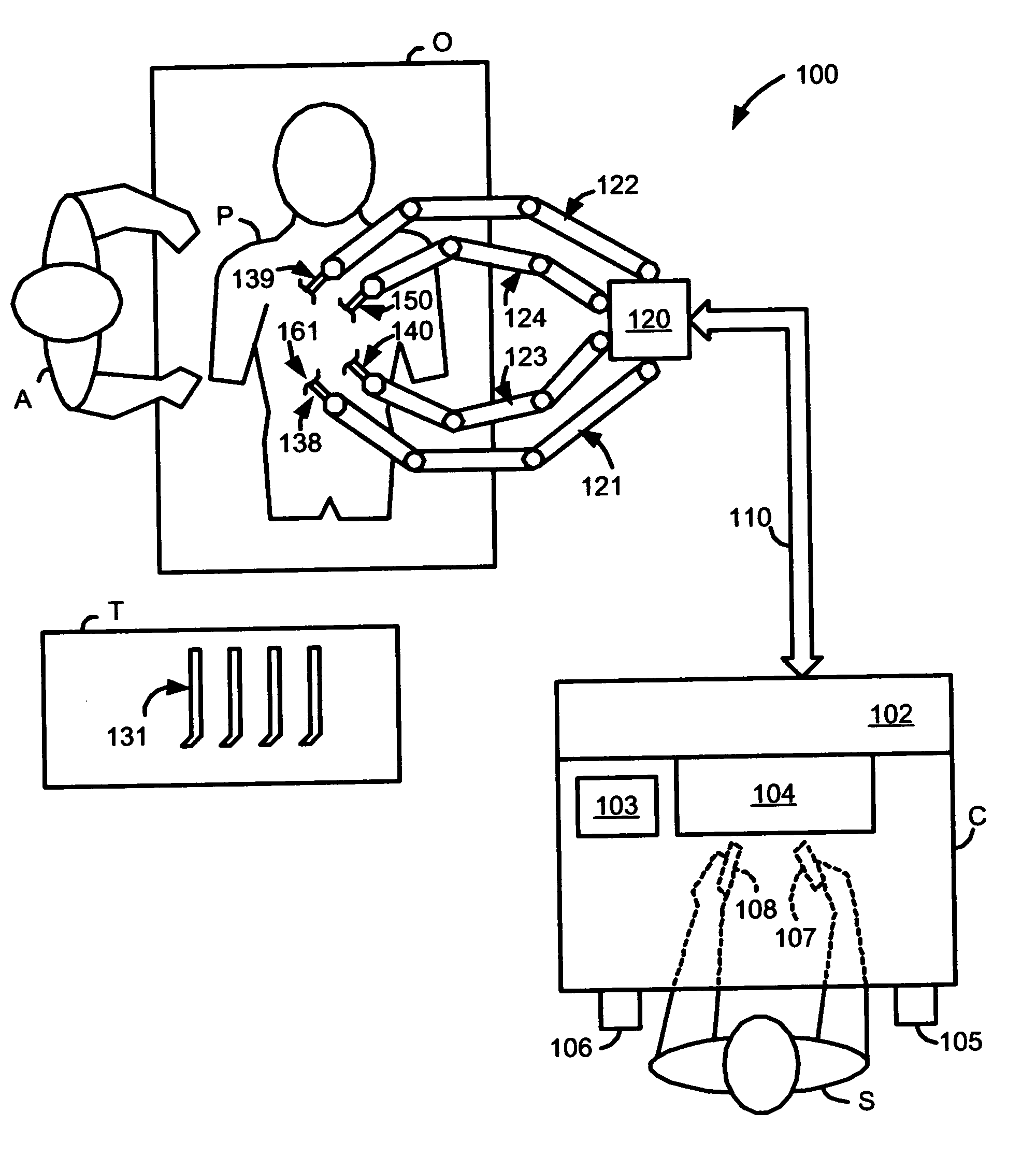
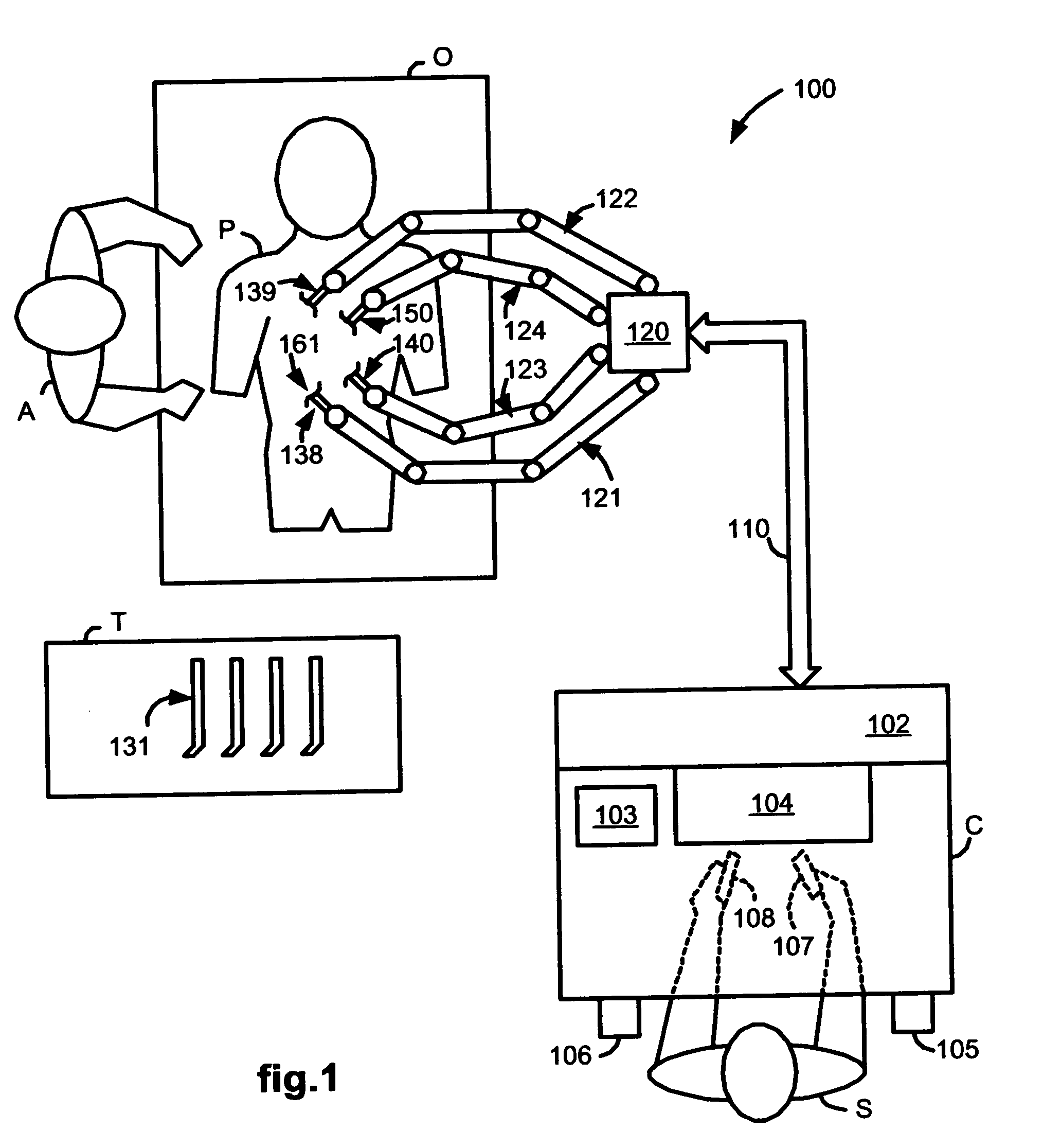
[0038]FIG. 1 illustrates, as an example, a top view of an operating room employing a robotic surgical system. The robotic surgical system in this case is a Laparascopic Ultrasound Robotic Surgical System 100 including a Console (“C”) utilized by a Surgeon (“S”) while performing a minimally invasive diagnostic or surgical procedure with assistance from one or more Assistants (“A”) on a Patient (“P”) who is reclining on an Operating table (“O”).

[0039] The Console includes a Master Display 104 (also referred to herein as a “Display Screen”) for displaying one or more images of a surgical site within the Patient as well as perhaps other information to the Surgeon. Also included are Master Input Devices 107 and 108 (also referred to herein as “Master Manipulators”), one or more Foot Pedals 105 and 106, a Microphone 103 for receiving voice commands from the Surgeon, and a Processor 102. The Master Input Devices 107 and 108 may include any one or more of a variety of input devices such as...


PUM


Abstract

A LUS robotic surgical system is trainable by a surgeon to automatically move a LUS probe in a desired fashion upon command so that the surgeon does not have to do so manually during a minimally invasive surgical procedure. A sequence of 2D ultrasound image slices captured by the LUS probe according to stored instructions are processable into a 3D ultrasound computer model of an anatomic structure, which may be displayed as a 3D or 2D overlay to a camera view or in a PIP as selected by the surgeon or programmed to assist the surgeon in inspecting an anatomic structure for abnormalities. Virtual fixtures are definable so as to assist the surgeon in accurately guiding a tool to a target on the displayed ultrasound image.

Description

CROSS REFERENCE TO RELATED APPLICATIONS [0001] This application claims priority to U.S. provisional application Ser. No. 60 / 688,019 filed Jun. 6, 2005, which is incorporated herein by reference.GOVERNMENT RIGHTS STATEMENT [0002] This invention was made with-Government support under Grant No. 1 R41 RR019159-01 awarded by the National Institutes of Health. The Government has certain rights to the invention.FIELD OF THE INVENTION [0003] The present invention generally relates to robotic surgical systems and in particular, to a laparoscopic ultrasound robotic surgical system useful for performing minimally invasive surgical procedures. BACKGROUND OF THE INVENTION [0004] Minimally invasive surgery offers many benefits over traditional open surgery techniques, including less pain, shorter hospital stays, quicker return to normal activities, minimal scarring, reduced recovery time, and less injury to tissue. Consequently, demand for minimally invasive surgery using robotic surgical systems...

Claims


Application Information

Patent Timeline
Patent Type & Authority Applications(United States)
IPC IPC(8): A61B17/00A61B8/00
CPCA61B8/00A61B8/12A61B8/4254A61B19/22A61B19/2203A61B2019/5291A61B2017/00203A61B2019/2223A61B2019/2292A61B2019/5276A61B2019/5289A61B19/5212A61B8/4245A61B8/4218A61B34/70A61B34/25A61B2090/364A61B90/361A61B34/30A61B34/76A61B90/03A61B2034/107A61B2090/378A61B2090/365A61B34/37G16H20/40G16H40/67A61B1/3132A61B8/461A61B2034/305A61B90/37
Inventor HASSER, CHRISTOPHER J.TAYLOR, RUSSELLCHOTI, MICHAELLEVEN, JOSHUA
Owner THE JOHN HOPKINS UNIV SCHOOL OF MEDICINE
Why Eureka
Try Eureka