Method for estimating a maintenance date and apparatus using the same

a technology of maintenance date and apparatus, applied in the field of semiconductor fabrication systems, can solve problems such as inconsistent data on maintenance plan and pm sheet, and achieve the effects of ensuring reliability and stability of equipment, reducing maintenance problems, and improving management efficiency

Active Publication Date: 2007-01-25
MACRONIX INT CO LTD
View PDF2 Cites 2 Cited by
  • Summary
  • Abstract
  • Description
  • Claims
  • Application Information

AI Technical Summary

Benefits of technology

[0012] For the purpose of decreasing maintenance issues, a powerful and user-friendly management system of preventive maintenance has been developed. The system integrates data of other information systems, and applies domain knowledge and professional methodology. The system supports dynamic forecasting of preventive maintenance (PM) dates and automatic alerting to improve the efficiency of management, to carry out all maintenance, and to ensure the reliability and stability of equipment. After integrating and analyzing the PM sheet that is stored in the system, the system can quickly and accurately provide managing reports and alerting reports. The system can also reuse data and improve the value of the data. Integrating with computerized equipment systems can eliminate the time it takes an engineer to approach the equipment, the time it takes to record parameters, and manual data errors that can occur by the engineer during recording. Also, when the maintenance period and specification of the maintenance item has changes, the manager can simultaneously update the plan of maintenance and the PM sheet; otherwise, the data on the plan of maintenance and the PM sheet can be inconsistent.

Problems solved by technology

Also, when the maintenance period and specification of the maintenance item has changes, the manager can simultaneously update the plan of maintenance and the PM sheet; otherwise, the data on the plan of maintenance and the PM sheet can be inconsistent.

Method used


Image

  • Method for estimating a maintenance date and apparatus using the same
  • Method for estimating a maintenance date and apparatus using the same
  • Method for estimating a maintenance date and apparatus using the same

Examples


second embodiment

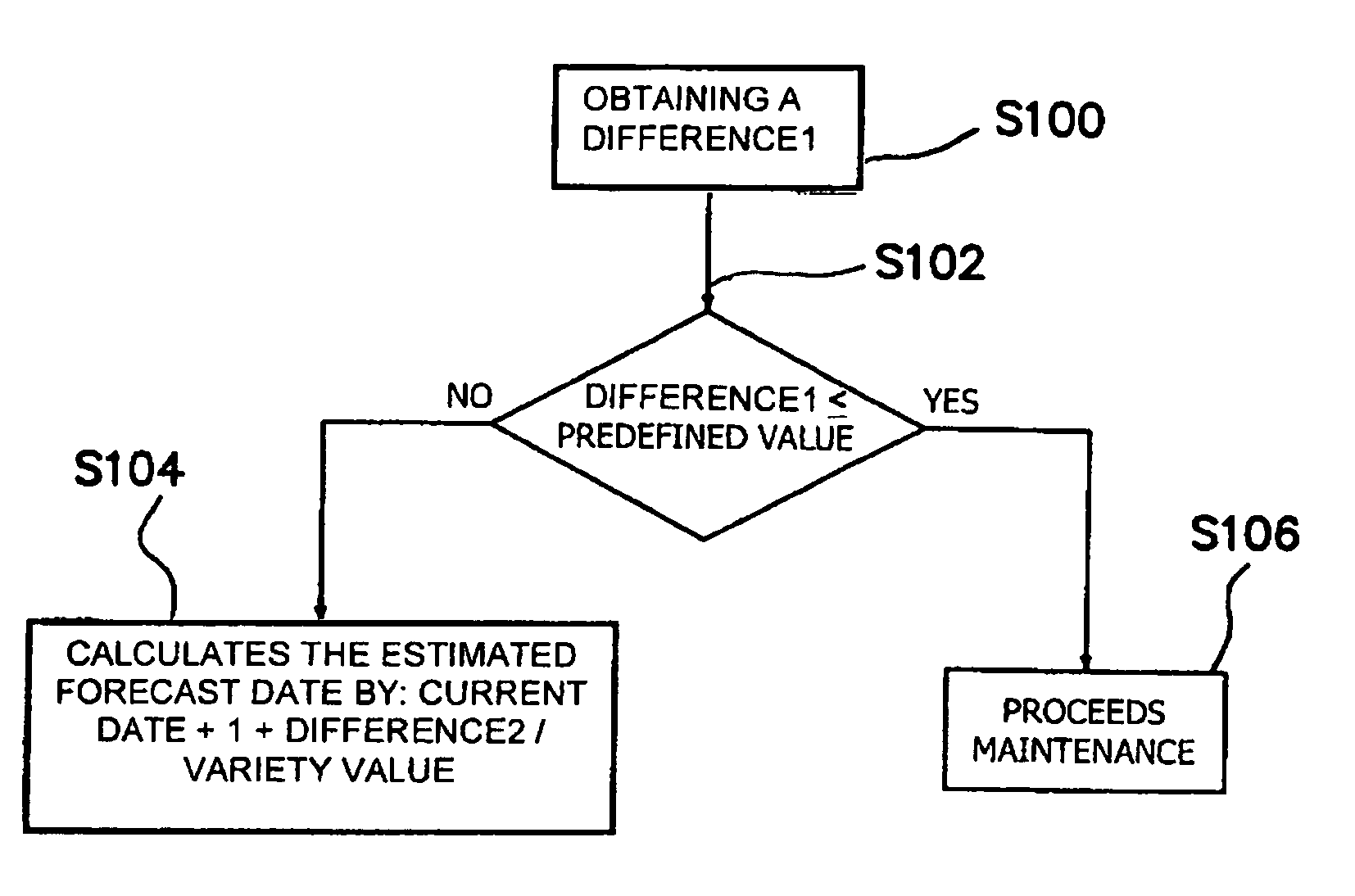
[0058]FIG. 1 also applies to a method for estimating a maintenance date by tracking multiple parameters according to the present invention. When multiple parameters are used, each parameter has its own associated detected value, maintenance value, predefined value, and variation value. The detected values are the values of the parameters taken from the tool. The maintenance values are typically the values of the parameters that the detected values are not allowed to exceed. Differences (S100) between maintenance values of parameters and detected values of the parameters are calculated for all parameters being tracked. The predefined values determine cut-off points for the differences. Comparisons (S102) are then made to determine whether or not a predetermined number of the differences is less than or equal to its corresponding predefined value. In the illustrated embodiment, the predetermined number is one so that comparisons (S102) are made to determine whether each difference (DI...

third embodiment

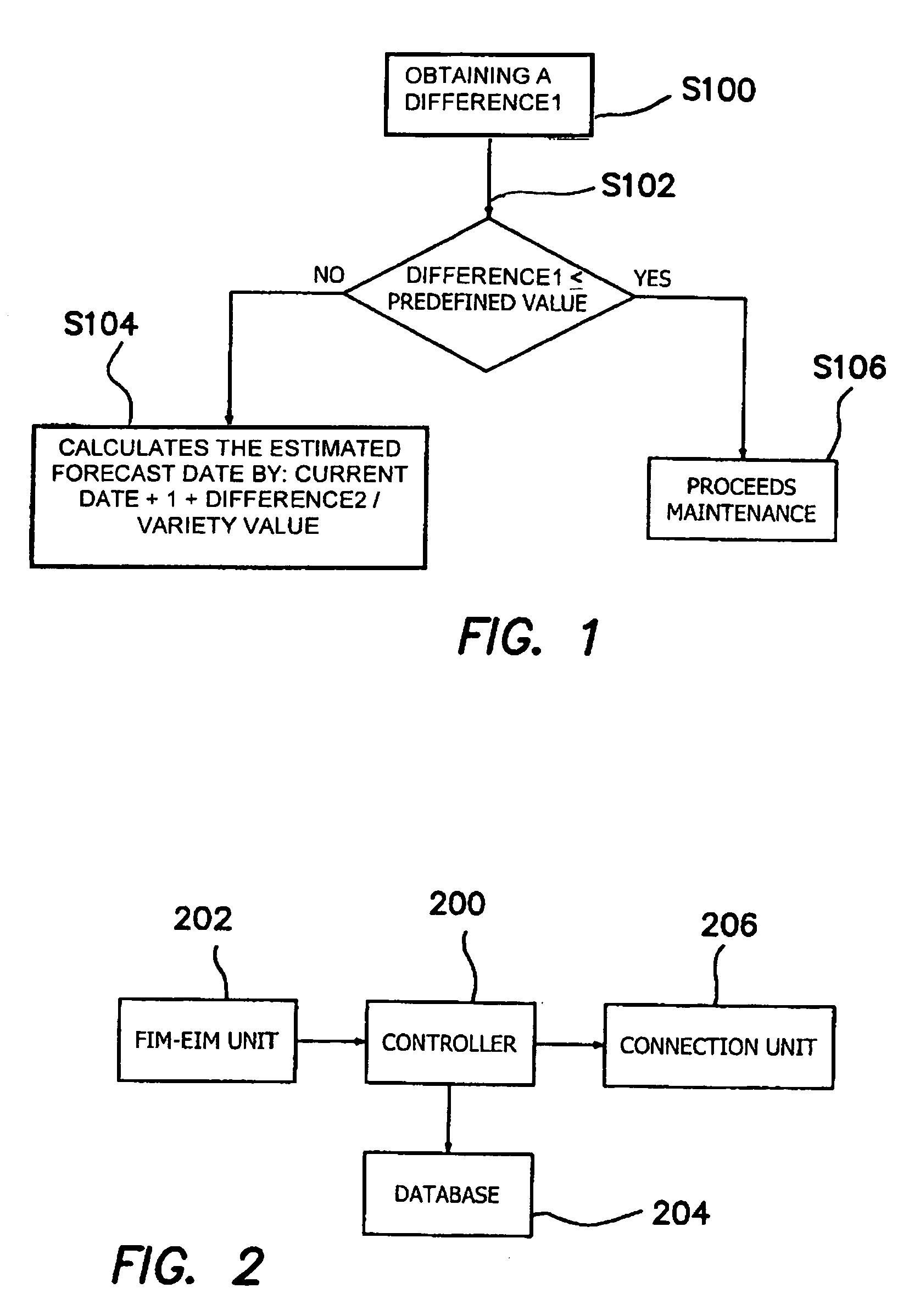
[0082]FIG. 2 is a modular diagram representing an apparatus for estimating a maintenance date according to the present invention. The apparatus comprises a connection unit 206, a database 204, a FIM-EIM (Fab Information Master-Equipment Information Master) unit 202, and a controller 200, and can be configured to be connected to at least one tool. The connection unit 206 is used to connect a tool to the apparatus to obtain a detected value of a parameter. The detected value of the parameter may also comprise a plurality of detected values of parameters, in which case the connection unit 206 will allow the plurality of detected values to be obtained from the tool. Also, the at least one tool may comprise a plurality of tools. In the illustrated embodiment, the connection unit 206 is an equipment automatic linking system through which the parameter of equipment can be automatically collected and stored to the TEMS system as shown in FIG. 28.

[0083] The database 204 stores a variation va...


PUM


Abstract

A method for estimating maintenance dates includes steps of obtaining one or more differences between detected values and maintenance values of parameters, and determining whether the differences are beyond predefined values. The method further includes a step of implementing or recommending an initiation of maintenance if any of the differences are beyond their respective predefined values. The method also includes a step of estimating the maintenance date according to the differences and variation values representing changes of the parameter per time unit for the tool, if none of the differences are beyond their respective predefined values. An apparatus for estimating maintenance date in this fashion is also presented. The apparatus includes a controller, a database, and a connection unit.

Description

CROSS-REFERENCE TO RELATED APPLICATIONS [0001] This application is a continuation in part of U.S. application Ser. No. 10 / 764,747, filed Jan. 26, 2004, the entire contents of which are hereby incorporated by reference.BACKGROUND OF THE INVENTION [0002] 1. Field of the Invention [0003] The present invention relates generally to semiconductor fabrication systems and, more particularly, to integrated maintenance scheduling systems. [0004] 2. Description of Related Art [0005] Equipment used in the semiconductor manufacturing industry can be extremely expensive and complicated. Engineers must typically execute preventive maintenance (PM) by following standard operation procedures (SOPs) to ensure reliability and stability of the manufacturing equipment. Because of the wide variety and large numbers of equipment, managing the maintenance of equipment manually can be inefficient. Mistakes arising from manual management as well as any lack of completion of the required maintenance procedure...

Claims


Application Information

Patent Timeline
Patent Type & Authority Applications(United States)
IPC IPC(8): G21C17/00G06F15/00G06Q10/00
CPCG06Q10/06
Inventor TSUNG, CHENG KUOMING, TSENG TSEFENG, HU CHIHCHAO, YEH MINGHSUAN, HO TSUNG
Owner MACRONIX INT CO LTD
Why Eureka
Try Eureka