

Riding Type Vehicle
a technology of riding type and transmission, which is applied in the direction of cycle equipment, transportation and packaging, cycle, etc., can solve the problems of deteriorating the function of cooling the inability to provide the exhaust duct, etc., and achieve the effect of improving the cooling of the v-belt type continuously variable transmission and reducing the size of the body cover
- Summary
- Abstract
- Description
- Claims
- Application Information
AI Technical Summary
Benefits of technology
Problems solved by technology
Method used
Image

Examples
first embodiment
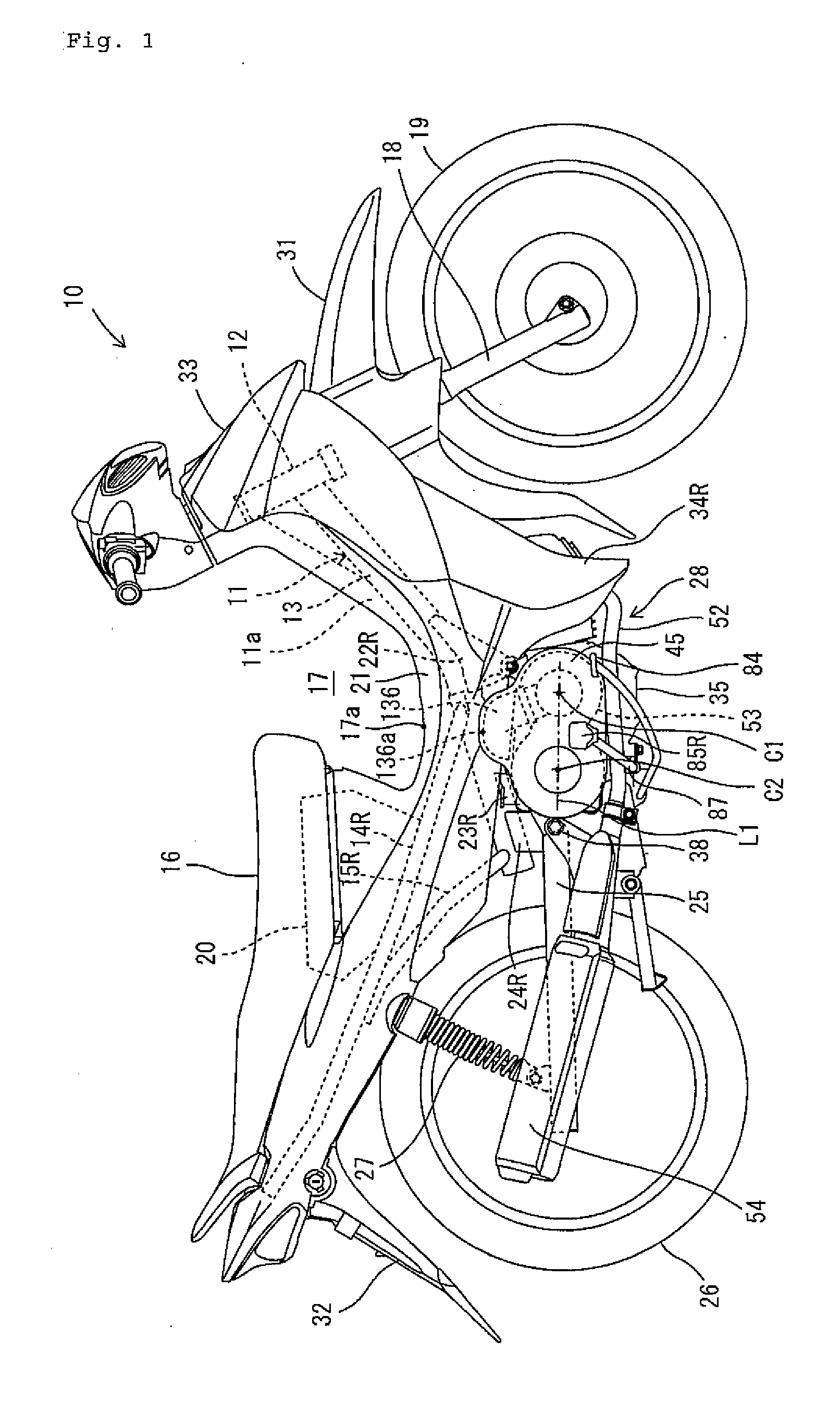
[0032] As shown by FIG. 1, a riding type vehicle according to the first embodiment of the invention is a motorcycle 10. The motorcycle 10 includes a body frame 11 and a seat 16 on which a passenger is seated. The motorcycle 10 is a so-called moped type motorcycle. That is, the motorcycle 10 is formed with a downward-recessed space 17 on a front side of the seat 16, and the passenger seated on the seat 16 straddles body frame 11. The ‘moped type’ mentioned here indicates only a shape of the vehicle, and does not limit the maximum speed, exhaust amount, the size of the vehicle and so on.
[0033] The riding type vehicle according to the invention is not limited to a moped but may be another type of motorcycle in which a fuel tank is disposed on a front side of the seat.
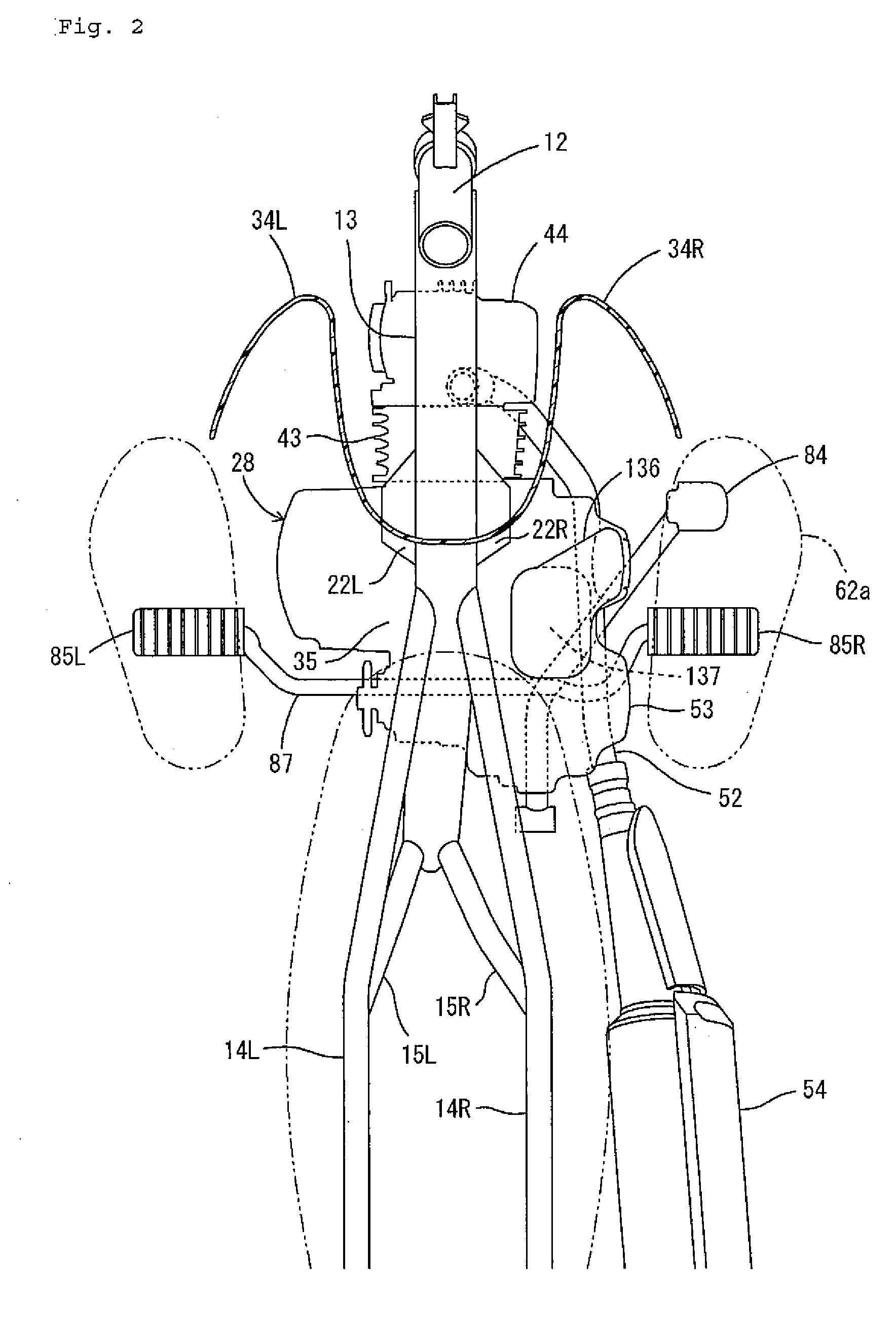
[0034] In the following description, the terms front, rear, left and right denote directions viewed from the perspective of a passenger seated on the seat 16. The body frame 11 includes a steering head pipe 12, a main fr...
second embodiment
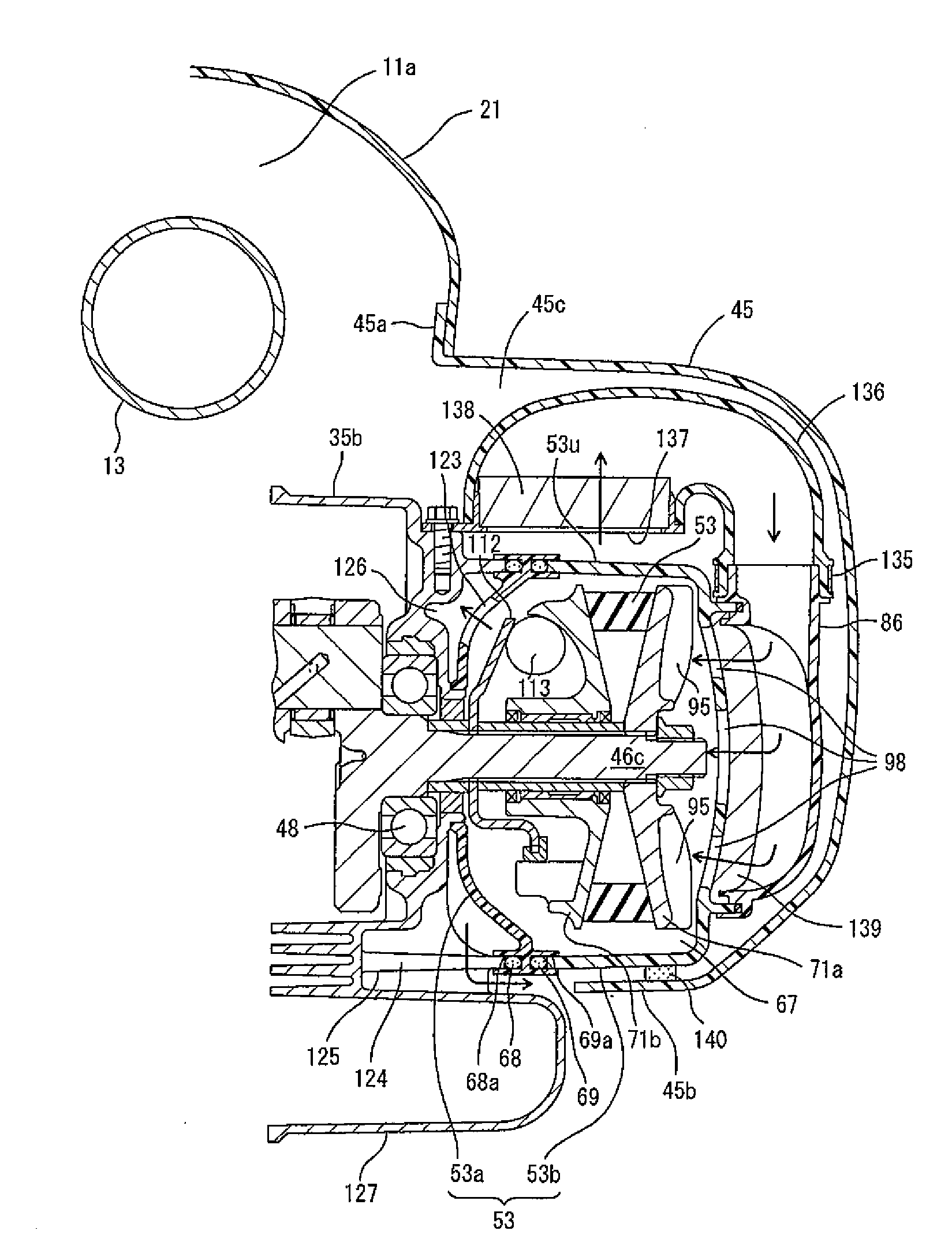
[0119] According to the first embodiment, the intake duct 136 partitioning the intake path is arranged on the outer side in the vehicle width direction of the center tunnel 11a and above the transmission case 53. However, the air path arranged on the outer side of the center tunnel 11a and above the transmission case 53 is not limited to the intake path. According to a second embodiment shown in FIGS. 11-13, an exhaust path for exhausting air after having cooled CVT 30 is disposed on the outer side in the vehicle width direction of the center tunnel 11a and above the transmission case 53.
[0120] As shown by FIGS. 11 and 12, according to the embodiment, a connecting tube 96 is formed on a front side portion (portion on a side of the primary sheave 71) of the outer side case 53b of the transmission case 53, and is connected with an intake duct 134. An upstream side of the intake duct 134 is connected to an air chamber 130. The air chamber 130 is arranged on a rear side of the leg shie...
third embodiment
[0134] In the first embodiment (refer to FIG. 9), body cover 21 and the cover 45 are formed separately and overlapped partially. Further, the intake duct 136 is arranged outward in the vehicle width direction as compared with the body cover 21. Also in the second embodiment (refer to FIG. 13), the body cover 21 and the cover 147 are formed separately and overlapped partially. Further, the exhaust duct 146 is arranged outward in the vehicle width direction as compared with the vehicle body cover 21. However, the body cover covering the center tunnel and the cover covering the duct may be formed integrally.
[0135] According to the third embodiment shown in FIG. 14, the body cover 21 and the cover 147 are formed integrally. In other words, the cover 147 forms a part of the body cover 21. Therefore, exhaust duct 146 is arranged outward in the vehicle width direction (a left and right direction of FIG. 14) as compared with the center tunnel 11a and positioned inward in the vehicle width ...
PUM
 Abstract
Description
Claims
Application Information