Method for manufacturing screen cylinder and screen cylinder
- Summary
- Abstract
- Description
- Claims
- Application Information
AI Technical Summary
Benefits of technology
Problems solved by technology
Method used
Image

Examples
Embodiment Construction
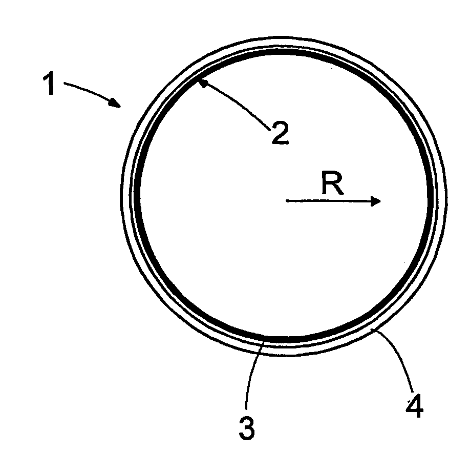
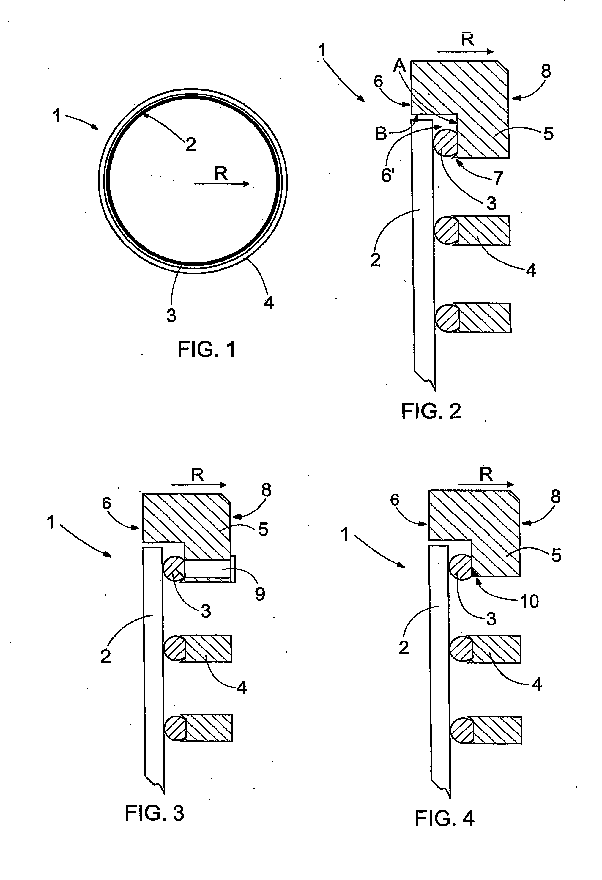
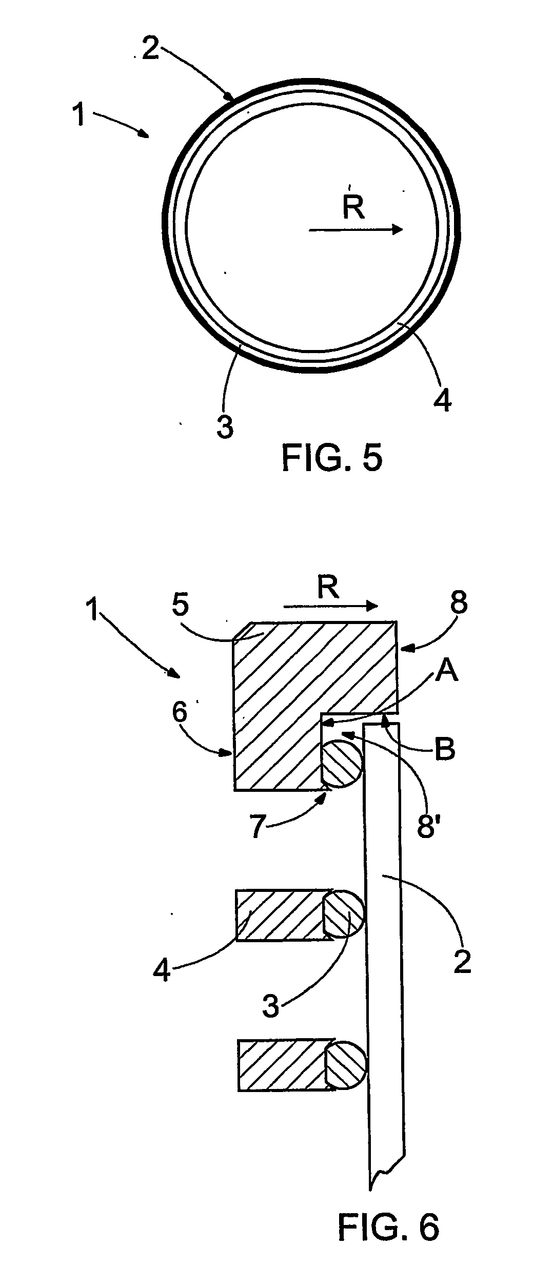
[0020]FIG. 1 is a schematic cross-sectional view of a screen cylinder 1 as seen from the end of the screen cylinder 1, and FIG. 2 is a schematic cross-sectional view of the screen cylinder of FIG. 1 in the axial direction of the screen cylinder 1. On the inner surface of the screen cylinder 1, there are screen wires 2 placed around the entire inner circumference of the screen cylinder 1 so that they form a screen surface. Between the screen wires 2, there are screen slots through which liquid and a desired part of the fibres is allowed to flow outside the screen cylinder 1 while slivers and too large fibres, fibre bundles and any other material to be screened remain on the inner surface of the screen cylinder 1 to be removed at its other end. The screen wires 2 are fastened to support wires 3 or rods 3 before the support rods 3 are bent in the shape of a ring in such a manner that a screen cylinder 1 having a suitable diameter is formed. The screen cylinder 1 can also be made in suc...
PUM
| Property | Measurement | Unit |
|---|---|---|
| Force | aaaaa | aaaaa |
| Circumference | aaaaa | aaaaa |
Abstract
Description
Claims
Application Information
PatSnap Eureka turns technology decisions into work you can execute. Powered by our Innovation Knowledge Graph, it runs expert workflows across engineering, life sciences, materials and intellectual property. Get your review-ready output in minutes.


