Apparatus and method for joining pipe ends together

a technology of apparatus and pipe ends, applied in the direction of soldering apparatus, manufacturing tools,auxillary welding devices, etc., can solve the problems of interference between the large head clamp, the weld to be made may contain welding errors, and the umbilicals are stretched and strained, and can only be repaired at high cost and substantial time loss

Active Publication Date: 2007-02-01
BIORHEOLOGICS CO LTD +1
View PDF4 Cites 27 Cited by
  • Summary
  • Abstract
  • Description
  • Claims
  • Application Information

AI Technical Summary

Benefits of technology

[0005] It is an object of the present invention to provide a welding apparatus and method in which one or more of the welding heads may have speeds which are different from one or more other welding heads, without the risk of damage to an umbilical.
[0006] It is another object of the present invention to reduce the risk of interference between a head clamp used for lowering the pipeline, and the welding equipment.

Problems solved by technology

In a welding process performed with the known apparatus, a problem may arise when one or more of the welding heads revolve around the pipe section at a different angular speed than one or more other welding heads.
Consequently, when different welding heads move at different speeds, they come at different distances from their corresponding sector of the rotary equipment holder, which may unduly stretch one or more of the umbilicals.
When this leads to damage of the umbilical, or a welding head which cannot perform its function properly, the weld to be made may contain welding errors which can only be repaired at high costs and at a substantial loss of time.
A disadvantage of the known apparatus in relation to this specific embodiment is interference between the large head clamp and the welding equipment being in fixed positions in the rotary equipment holder.

Method used


Image

  • Apparatus and method for joining pipe ends together
  • Apparatus and method for joining pipe ends together
  • Apparatus and method for joining pipe ends together

Examples


Embodiment Construction

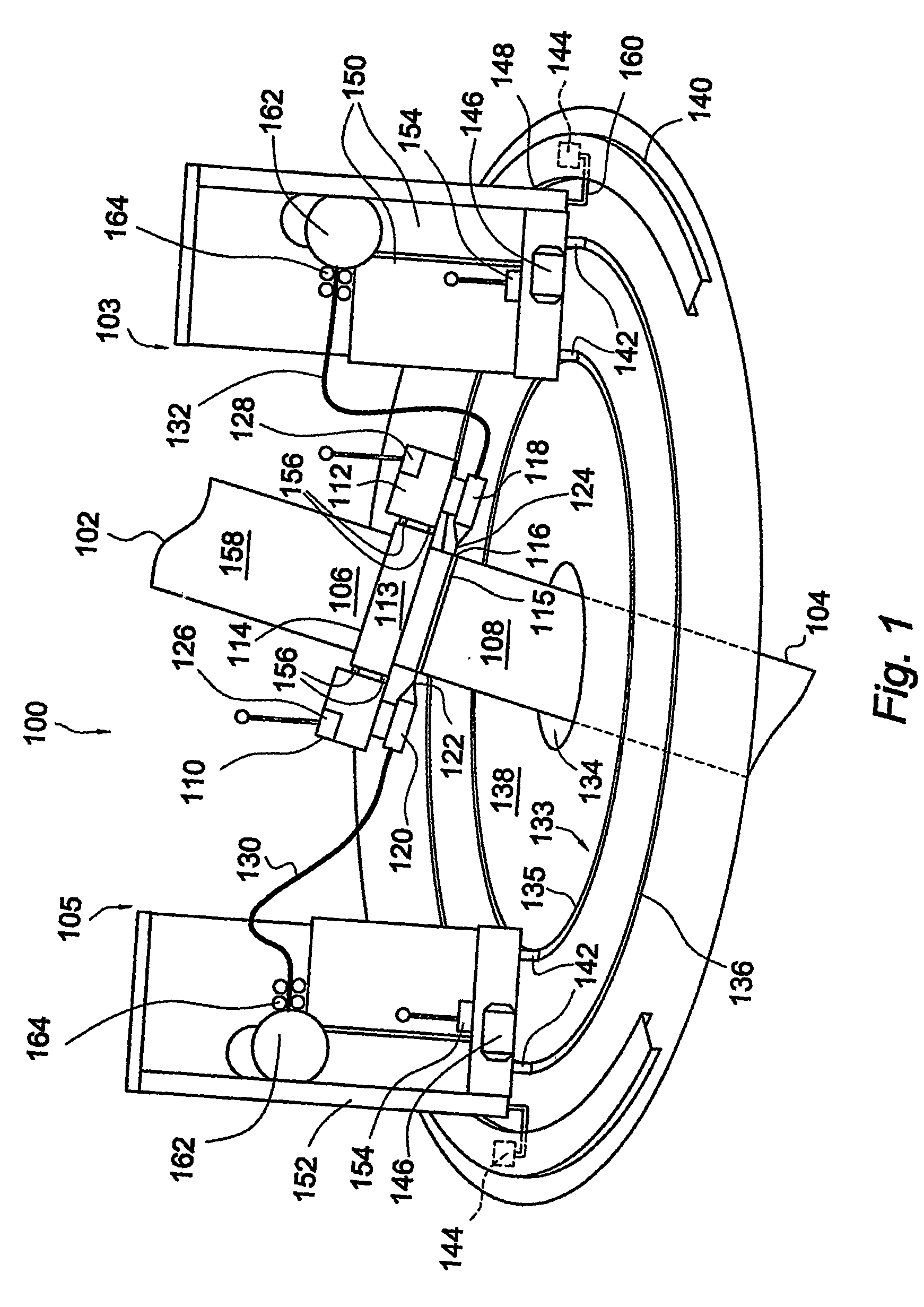
[0065]FIG. 1 shows a welding apparatus 100, for joining an upper pipe section 102 to a lower pipe section 104. The apparatus 100 may be placed inside a housing (not shown). The two pipe sections 102 and 104 are substantially upright, and have an outer pipe surface 158. The upper pipe section 102 has a lower end 106 and the lower pipe section 104 has an upper end 108. The pipe sections are placed in a position, in which the ends 106 and 108 abut. The pipe sections 102, 104 usually have a circular cross-section, but e.g. an oval or elliptical cross-section is also possible.

[0066] The abutting lower end 106 and the upper end 108 have been pre-treated prior to the welding process, such that both ends have exactly the required shape. The abutting pipe ends 106, 108 may define a groove (not shown). The groove may have a substantial V-shape or a U-shape, or any other shape which is suitable to serve as a basis for a welded connection. The abutting pipe ends 106, 108 or the groove formed t...


PUM

PropertyMeasurementUnit
areaaaaaaaaaaa
speedaaaaaaaaaa
circumferenceaaaaaaaaaa

Abstract

A method and apparatus for joining pipe sections (102, 104) together to form an underwater pipeline. The pipe sections (102, 104) are in an abutting position and have a generally vertical orientation. An upper end (108) of the most recently joined pipe sections (104) is to be welded to a lower end (106) of a new pipe section (102). The apparatus comprises at least two welding equipment carriers (148, 152) and at least two welding heads (110, 112). Each welding head is connected to an equipment carrier (148, 152) by means of at least one umbilical (130, 132). The apparatus further comprises a welding head guide assembly (113) which is adapted to be fixed to one of said upper of lower pipe sections. The welding head guide assembly (113) guides the welding heads about the pipe sections (102, 104). The apparatus further comprises a guiding device (133) which guides the welding equipment carriers (148, 152) around said welding area (115). The welding equipment carriers (148, 152) are movable independently from one another.

Description

FIELD OF THE INVENTION [0001] The present invention relates to an apparatus and method for joining pipe ends together, such as in the offshore industry where in deep water, pipe sections are joined together vertically to form a pipeline which is lowered from a vessel to an underwater bottom. In such a pipe laying method, which is commonly referred to as a J-lay method, a plurality of pipe sections, welded to one another, together forming a part of the pipeline, hang down from a vessel in a substantially vertical direction, where an upper end of the most recently joined pipe section is to be welded to a lower end of a new pipe section being lined up above said upper end. In a specific embodiment of the J-lay method, the ends of the pipe sections are provided with collars for easier handling of the pipe sections. Upon completion of a weld, the end of the pipeline is gripped by the collar with a head clamp and lowered to just below the welding position to prepare for a new pipe section...

Claims


Application Information

Patent Timeline
Patent Type & Authority Applications(United States)
IPC IPC(8): A47J36/02B23KB23K9/028B23K26/28B23K37/02
CPCB23K9/0286B23K26/285B23K2201/10B23K37/0276B23K37/0211B23K26/282B23K2101/10
Inventor KOPPERT, FRITS-JANZANDWIJK, CORNELIS VAN
Owner BIORHEOLOGICS CO LTD
Why Eureka
Try Eureka