Quiet airplane configuration

a technology of airplane configuration and flight control surface, which is applied in the direction of aircraft/engines, fuselages, transportation and packaging, etc., can solve the problems of limiting the ability to expand services, commercial aircraft will reach or negatively exceed certain noise limitations, and the major exterior control components of transport aircraft are not advantageously located, so as to reduce the acoustic signature

Inactive Publication Date: 2007-02-01
THE BOEING CO
View PDF12 Cites 38 Cited by
  • Summary
  • Abstract
  • Description
  • Claims
  • Application Information

AI Technical Summary

Benefits of technology

[0005] The teachings of the present invention provide an aircraft that reduces acoustic signature, most notably flyover and sideline noise, and infra red signature. The aircraft engines are located forward of the aircraft trailing edge and elevons of the aircraft on top of the blended wing and fuselage. Vertical aerodynamic flight control surfaces are located at least on each side of the engines to provide lateral shielding to reflect noise and heat upward and away from the aircraft and the ground. Because the jet engines may be located on top and towards the center of a blended wing body, flyover noise and heat are also shielded by the blended wing body.
[0006] Furthermore, the teachings are such to move the exhaust jet noise closer to the engine nozzle exit by increasing the nozzle exit flow shear perimeter and creating vortex generating shapes about the engine perimeter. By moving the noise generation closer to the engine exit, the elevons below and aft of the engines shield noise and reduce the radiant heat generated by the engines. Finally, because the engines are moved forward on the blended wing, a reactive downward force is generated against the top of the blended wing forward of the main landing gear when, upon landing, reverse thrust meets onrushing air and creates a vertical wall jet. The vertical wall jet reduces aircraft lift while the downward force generates a favorable nose down pitching moment about the main landing gear.

Problems solved by technology

However, with increasingly more air traffic growth, the number of airplanes and flight operations with local government regulations and restrictions will be limiting the ability to expand services for public demand.
With increasing sizes of engines, airplanes, and payloads, commercial aircraft will reach or negatively exceed certain noise limitations.
In this regard, transport aircraft do not have their major exterior control components advantageously located to significantly reduce such noise and infrared signatures.
Furthermore, due to the current locations of engines on aft fuselage mounted engine configurations relative to the landing gear, during reverse thrusting, aircraft may have a tendency to experience nose wheel lift off during reverse thrusting, which limits the level of reverser thrust possible.

Method used


Image

  • Quiet airplane configuration
  • Quiet airplane configuration
  • Quiet airplane configuration

Examples


Embodiment Construction

[0019] The following description of the preferred embodiments is merely exemplary in nature and is in no way intended to limit the invention, its application, or uses.

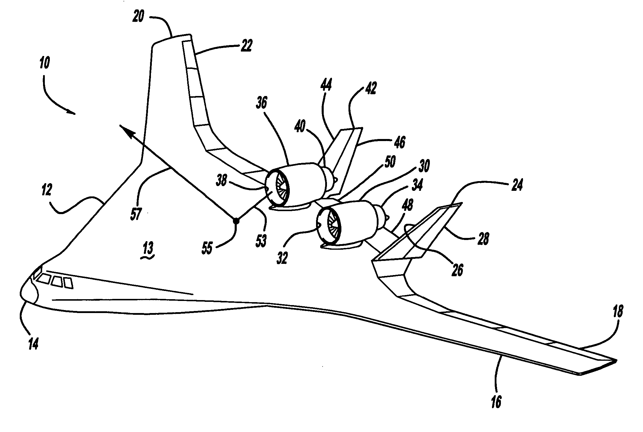
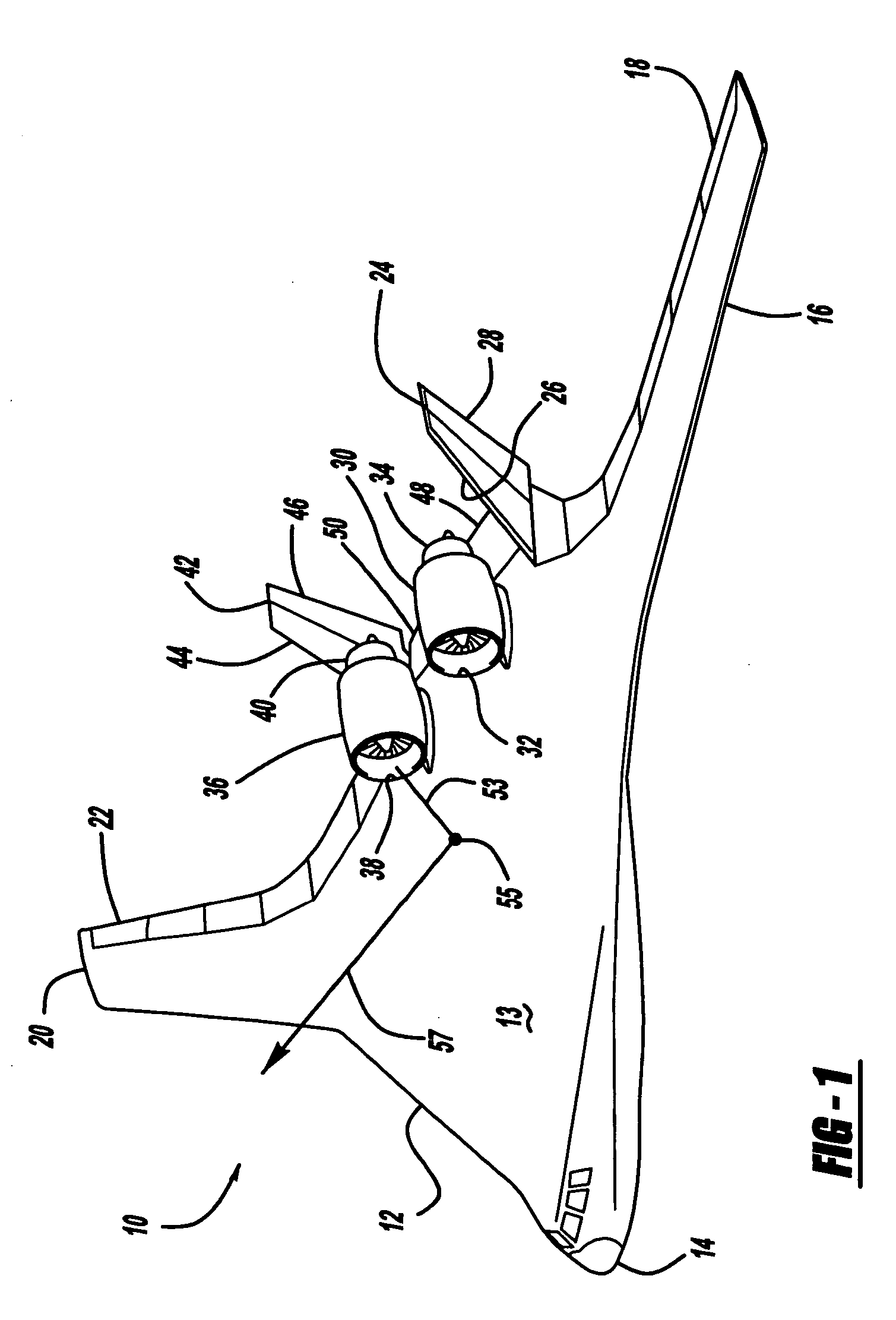
[0020] With reference to FIG. 1, an aircraft and its component configuration according to the teachings of the present invention is generally depicted at reference numeral 10. With continued reference to FIG. 1, the aircraft 10 shown is a blended wing body (BWB) aircraft and is used throughout the description as an example of an aircraft upon which the configuration of the teachings of the present invention could be used; however, other types of aircraft, such as traditional tube and wing configurations could be configured similarly to the teachings of the present invention.

[0021] Continuing with reference to FIG. 1, the aircraft 10 has a nose section 14 at the leading end of a blended fuselage and wing 12. The blended fuselage and wing 12 has an expansive, generally flat top wing surface area 13 upon which other str...


PUM


Abstract

A blended wing aircraft reduces forward, aft, and sideline flyover noise and heat energy by reflecting it upward using the wing and vertical stabilizers positioned just outboard of the engines. The engines are located on top of the wing and forward of the trailing edge of the wing with the aft portion of the engines located over the wing. The nozzle exit perimeter is increased and shaped to increase shear and create vortices to move noise generation over the wing to cause the noise to be reflected upward off the wing and upward off of the canted vertical stabilizers. Engine thrust reversers cause the forwardly mounted engine's thrust to be directed toward the front of the aircraft in such a way as to create a download forward of the main landing gear to also secure the front landing gear.

Description

FIELD OF THE INVENTION [0001] The present invention relates to the arrangement of propulsion systems and vertical aerodynamic flight control surfaces of an aircraft to reduce ground detectable acoustic signatures and infra red heat signatures of the aircraft. BACKGROUND OF THE INVENTION [0002] Various configurations for the exterior components of an aircraft are known. Many of such aircraft include different configurations of control components such as engines, wings, elevators, ailerons, and rudders. Related to the configuration of such components, every aircraft has a flyover noise signature, a sideline noise signature, known as acoustic signatures, and an infrared heat signature associated with it. The intensities of such signatures are dependent upon the specific component configuration of the specific aircraft. [0003] For many commercial applications, the current flyover noise, sideline noise, and infrared signatures are acceptable and meet specific airport and FAA requirements...

Claims


Application Information

Patent Timeline
Patent Type & Authority Applications(United States)
IPC IPC(8): B64C1/00
CPCB64C39/10B64C2039/105F02K1/48F02K1/386B64D27/16B64D27/12B64D27/14B64D27/18B64D27/20F02K1/44
Inventor KAWAI, RONALD T.ODLE, RICHARD C.
Owner THE BOEING CO
Why Eureka
Try Eureka