Hand shield system and method for welding

a shield system and hand shield technology, applied in the field of hand shield systems, to achieve the effect of reducing the amount of radiant heat continuously emitted during welding operations

Inactive Publication Date: 2012-04-26
DAWSON RICHARD
View PDF5 Cites 7 Cited by
  • Summary
  • Abstract
  • Description
  • Claims
  • Application Information

AI Technical Summary

Benefits of technology

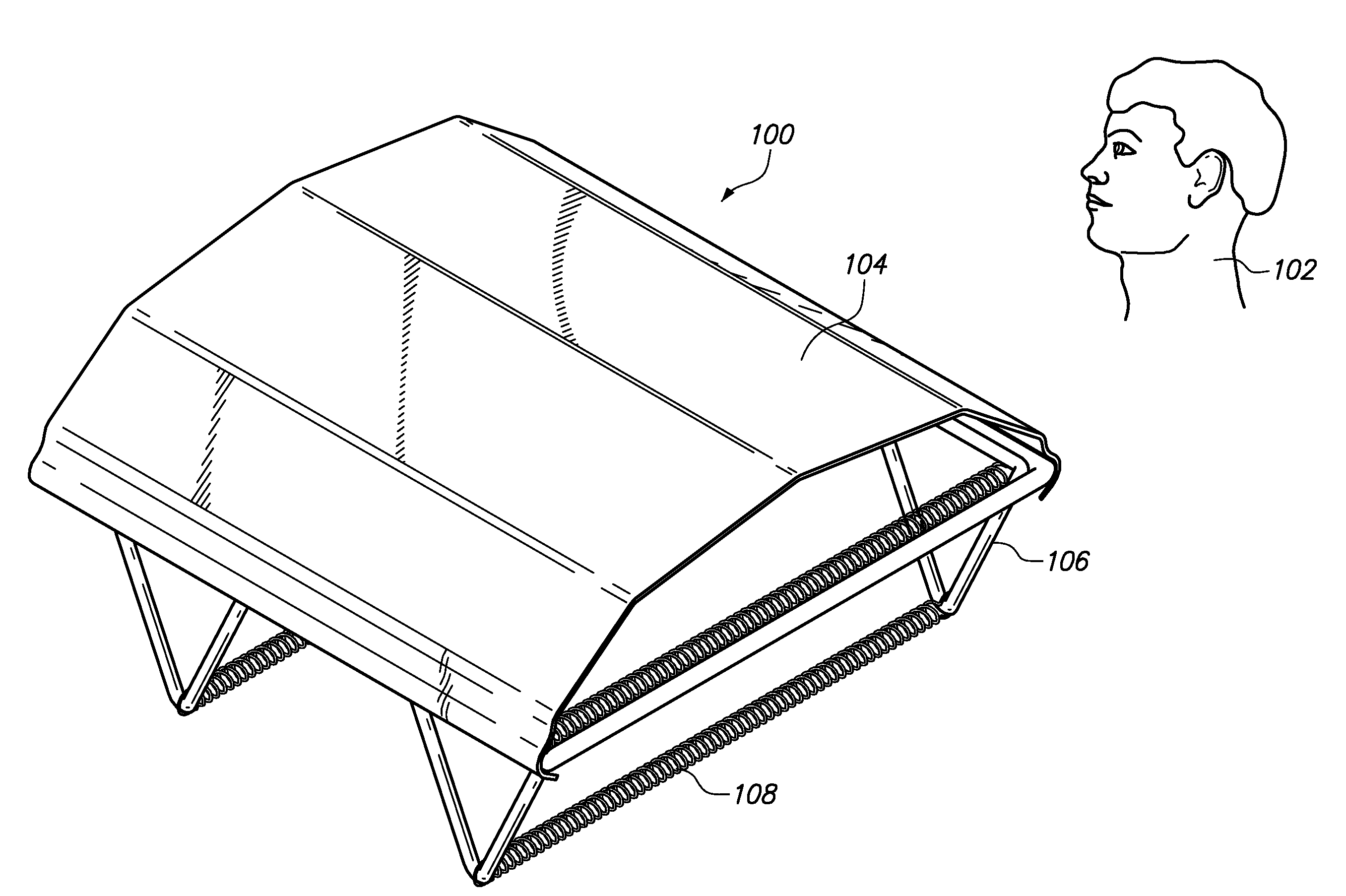
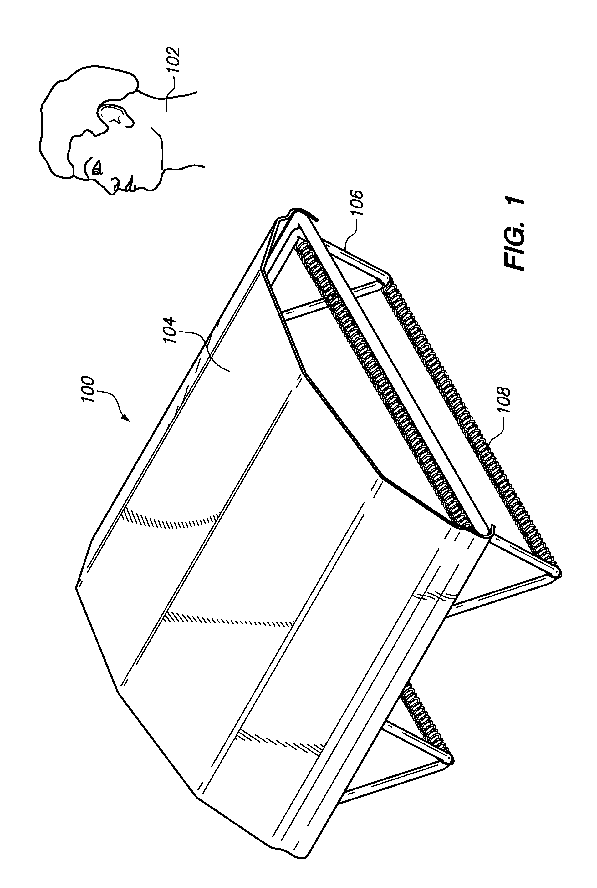
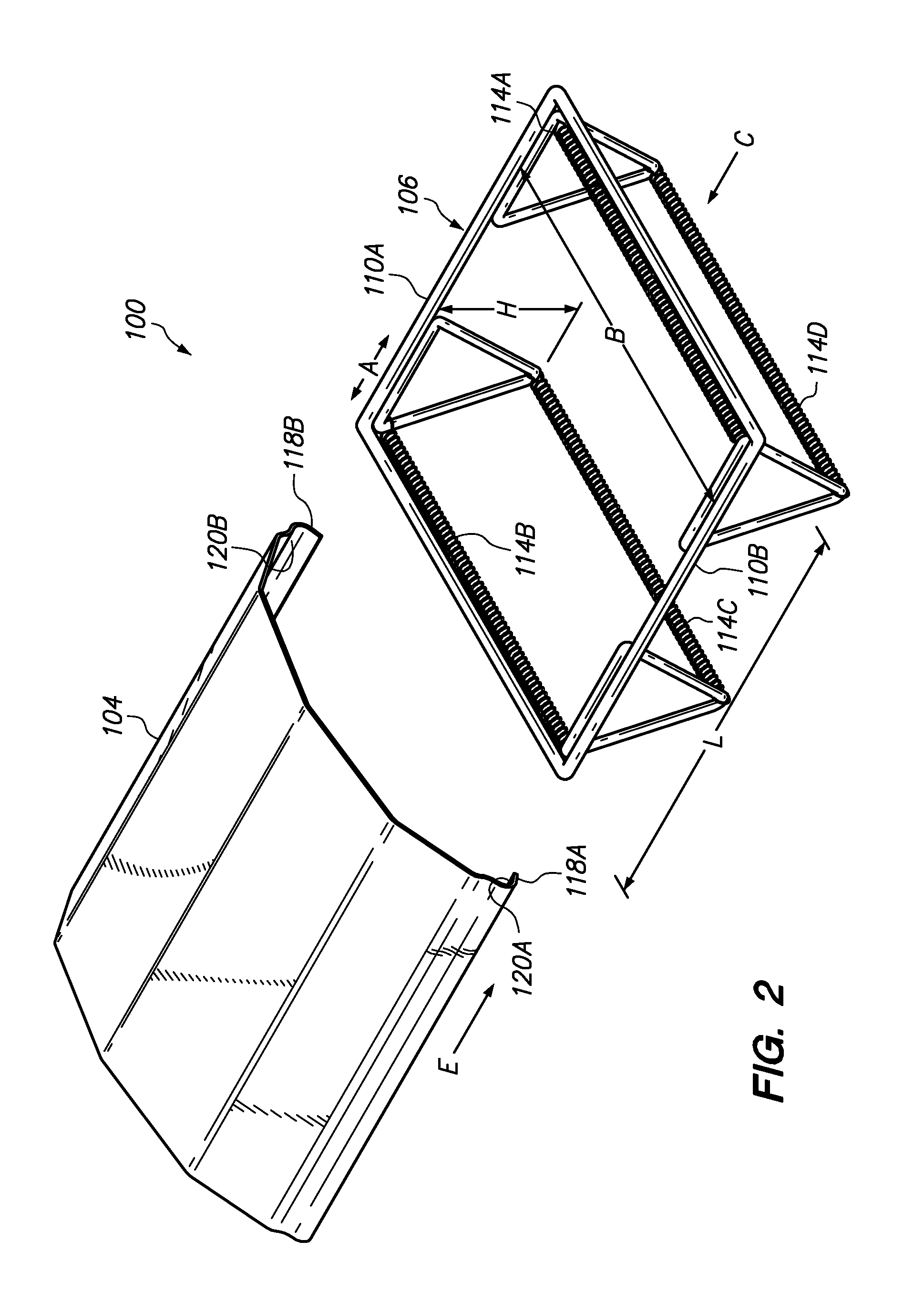
[0010]A plate, preferably made of polished aluminum, includes grooves that can receive the top frame of the rigid frame. The grooves engage the top frame so that the plate is slide-able along over the top frame forming a shield to cover and protect said user's gloved hand from slags and torch burns and the like during a welding operation.
[0011]As the welding operation intensifies, and unlike conventional systems, the radiant heat slag, flames and molten pool do not burn through the gloved hands of the user as the plate shields the glove to provide significant protection. Moreover, transmission of radiant heat that is continuously emitted during such welding operations is considerably reduced by an air gap between the plate and the user's gloved hand. Welders need not discontinue or rush through welding operations as in conventional systems. If the welding operation is overhead, the plate is slid further out to shield against flames and molten pools that fall toward the welder.

Problems solved by technology

As the welding operation intensifies or as the duration becomes longer, the radiant heat slag, flames and molten pool often burn through the aluminum-glazed pad and / or the glove subjecting the user to burns.

Method used


Image

  • Hand shield system and method for welding
  • Hand shield system and method for welding
  • Hand shield system and method for welding

Examples


Embodiment Construction

[0024]Reference will now be made in detail to the embodiments of the invention, examples of which are illustrated in the accompanying drawings. While the invention will be described in conjunction with the preferred embodiments, it will be understood that they are not intended to limit the invention to these embodiments. On the contrary, the invention is intended to cover alternatives, modifications and equivalents which may be included within the spirit and scope of the invention as defined by the appended claims. Furthermore, in the following detailed description of the present invention, numerous specific details are set forth to provide a thorough understanding of the present invention. However, it will be obvious to one of ordinary skill in the art that the present invention may be practiced without these specific details. In other instances, well-known methods, procedures, components, and circuits have not been described in detail as to not unnecessarily obscure aspects of the...


PUM

PropertyMeasurementUnit
lengthaaaaaaaaaa
flexibleaaaaaaaaaa
dimensionsaaaaaaaaaa

Abstract

A hand-held shield for welding. The shield includes a rigid metal frame for receiving a user's gloved hand. A substantially rectangular plate is detachably engaged over the rigid metal frame forming a shield to cover and protect the user's gloved hands from slags, molten flames and the like that are typically encountered during welding operations.

Description

BACKGROUND OF THE INVENTION[0001]The present invention relates to hand protective systems and more specifically to hand protective systems associated with welding operations.[0002]Discrete metal pieces such as steel and wrought iron often need to be combined as necessary to implement any particular project. Horizontal and vertical steel pieces might need to be integrated when they intersect at a corner, for example.[0003]The process most often employed for attaching such discrete metal pieces is welding. Typical welding operations begin by powering electric arc welding and oxyacetylene-powered blow torches to high optimum welding temperatures. Such optimum welding temperatures begin at 350 and can reach extremely high temperatures of 6300 degrees. Next, the welder must wear gloves typically made of leather or fire-retardant fabrics. In some instances, a thin aluminum glazed pad attached to a welder's hand by elastic straps can be worn over the gloves.[0004]Only then can the welding ...

Claims


Application Information

Patent Timeline
Patent Type & Authority Applications(United States)
IPC IPC(8): B23K26/00A41D13/08
CPCA41D13/084F16P1/06B23K37/006B23K9/321
Inventor DAWSON, RICHARD
Owner DAWSON RICHARD
Why Eureka
Try Eureka