Engine device and stationary work machine having same mounted thereon

a technology of engine and work machine, which is applied in the direction of machines/engines, mechanical equipment, exhaust treatment electric control, etc., can solve the problems of difficult stably assembling the electrical components attached to the exhaust-gas purification device are likely to fail, and the exhaust-gas purification device is significantly heavier than the sound absorber. , to achieve the effect of reducing the malfunction of at least one electrical component, reducing the influence of radiant heat, and reducing the influence of hea

Inactive Publication Date: 2017-01-12
YANMAR POWER TECHNOLOGY CO LTD
View PDF6 Cites 7 Cited by
  • Summary
  • Abstract
  • Description
  • Claims
  • Application Information

AI Technical Summary

Benefits of technology

[0023]According to the embodiment of the invention according to the fifth aspect of the present invention, the at least one electrical component is disposed at a position located at the outside of the exhaust-gas purification device and located at an upstream side in a direction in which the exhaust gas moves in the inside of the exhaust-gas purification device. This configuration, therefore, reduces the influence of heat from the exhaust-gas purification device and the engine, and as a result, reduces the malfunction of the at least one electrical component due to the heat. Further, in this configuration, the at least one electrical component is disposed at a side where the heat capacity is smaller, and thus, this disposition reduces the influence of radiant heat from the exhaust-gas purification device on the at least one electrical component.
[0024]According to the embodiment of the invention according to the sixth aspect of the present invention, the exhaust-gas purification device is coupled to the exhaust manifold, disposed at one side of the engine, via the exhaust-gas introduction unit, and with the support bracket, secured to one end face of the exhaust-gas purification case of the exhaust-gas purification device, the at least one electrical component is disposed at a position outside the exhaust-gas introduction unit. In this configuration, therefore, the at least one electrical component is disposed at a position located at a more upstream side than the exhaust-gas purification device and located distanced from the exhaust-gas purification device, and this disposition reduces the influence of conductive heat and radiant heat from the exhaust-gas purification device, and as a result, reduces the malfunction of the at least one electrical component due to the heat.
[0025]According to the embodiment of the invention according to the seventh aspect of the present invention, the cooling fan is disposed at one side of the engine, the flywheel housing is disposed at the other side of the engine. Further, the flywheel is coupled to the work unit so as to transfer engine power to the work unit, and the exhaust-gas purification device is disposed at the upper-face side of the flywheel housing to allow the exhaust-gas purification device to be located above the work unit. This configuration, therefore, realizes a highly rigid structure for supporting the exhaust-gas purification apparatus with the flywheel housing, which is a highly rigid component for the engine, and as a result, reduces the damage on the exhaust-gas purification apparatus due to the vibration and any other damage cause. Further, a space above the work unit is utilized as an installation space of the exhaust-gas purification device, and this configuration increases the utilization efficiency of an inside space of the chassis, which contains the engine device.
[0026]According to the embodiment of the invention according to the eighth aspect of the present invention, in a stationary work machine including a work unit serving as a compressor or a power generator, the engine device according to the embodiment of the seventh aspect of the present invention, a chassis containing the work unit and the engine device, a ventilation opening configured to bring the inside and the outside of the chassis into communication with each other is disposed in an upper face of the chassis so as to allow the exhaust-gas purification device to face the ventilation opening itself from below. In this configuration, therefore, excessively heated air generated in the exhaust-gas purification device is discharged to the outside of the chassis via the ventilation opening, and thus, this configuration contributes to the optimization of a heat balance inside the chassis.
[0027]According to the embodiment of the invention according to the ninth aspect of the present invention, the stationary work machine includes a shutter plate disposed inside the chassis and configured to, when the engine is in a driven state, allow cooling wind from the cooling fan to shut the ventilation port, and to, when the engine is in a stop state, allow the ventilation port to open by weight of the shutter plate itself. Accordingly, when the engine is in a driven state, this configuration certainly blocks the invasion of dust and any other fine material into the chassis through the ventilation opening. After the stop of the engine, heated air generated in the exhaust-gas purification device is discharged to the outside of the chassis via the ventilation opening, and this configuration reduces the occurrence of a situation in which the heated air is confined inside the chassis. Thus, this configuration reduces the occurrence of heat damage on the exhaust-gas purification device itself, the chassis, and any other equipment.
[0028]According to the embodiment of the invention according to the tenth aspect of the present invention, in a stationary work machine including a work unit serving as a compressor or a power generator, the engine device according to the embodiment of the seventh aspect of the present invention, a chassis containing the work unit and the engine device, a ventilation opening configured to bring the inside and the outside of the chassis into communication with each other is disposed in an upper face of the chassis so as to allow the exhaust-gas purification device to face the ventilation opening itself from below. Further, an actuator configured to perform opening / closing drive of the shutter plate is provided, and the actuator is configured to, upon ON-operation of the key switch, drive the shutter plate so as to allow the shutter plate to shut the ventilation opening, and to, upon OFF-operation of the key switch, drive the shutter plate so as to allow the shutter plate to open the ventilation opening. Accordingly, just like the embodiment of the third aspect of the present invention, when the engine is in a driven state, this configuration blocks the invasion of dust and any other fine material into the chassis through the ventilation opening. After the stop of the engine, heated air generated in the exhaust-gas purification device is discharged to the outside of the chassis via the ventilation opening, and thus, this configuration reduces the occurrence of a situation in which the heated air is confined inside the chassis. Accordingly, this configuration reduces the occurrence of heat damage on the exhaust-gas purification device itself, the chassis, and any other equipment.

Problems solved by technology

By the way, when such an exhaust-gas purification device is installed, even though just a method of disposing an exhaust-gas purification device in substitution for a sound absorber (muffler) is employed, the exhaust-gas purification device is significantly heavier than the sound absorber.
For this reason, even though a supporting structure for a sound absorber in a construction machine disclosed in Japanese Unexamined Patent Application Publication No. 2007-182705 is employed as a supporting structure for an exhaust-gas purification device, it may be difficult to stably assemble the exhaust-gas purification device.
For this reason, electrical components attached to the exhaust-gas purification device are likely to fail because of heat from the exhaust-gas purification device and an engine.
Particularly when such a failure occurs in a temperature sensor and / or a pressure sensor, it is not easy to confirm a state of the exhaust-gas purification device, and thus, a clogging state inside the device is not eliminated, and as a result, a failure, such as an engine stall, occurs.
For this reason, it is difficult to reduce the occurrence of heat damage on the exhaust-gas purification device itself, the machine chassis, and any other equipment.

Method used


Image

  • Engine device and stationary work machine having same mounted thereon
  • Engine device and stationary work machine having same mounted thereon
  • Engine device and stationary work machine having same mounted thereon

Examples


Embodiment Construction

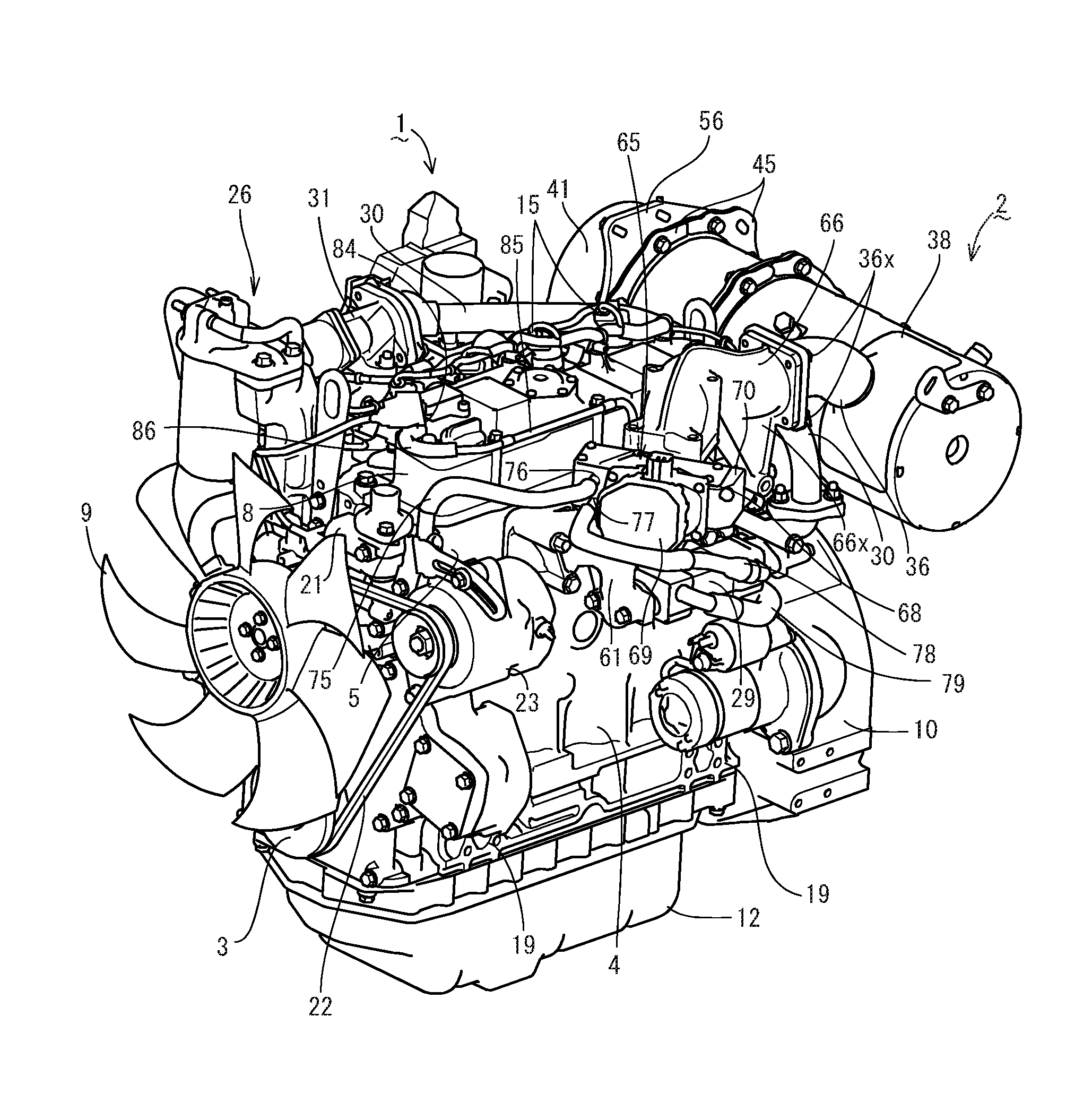
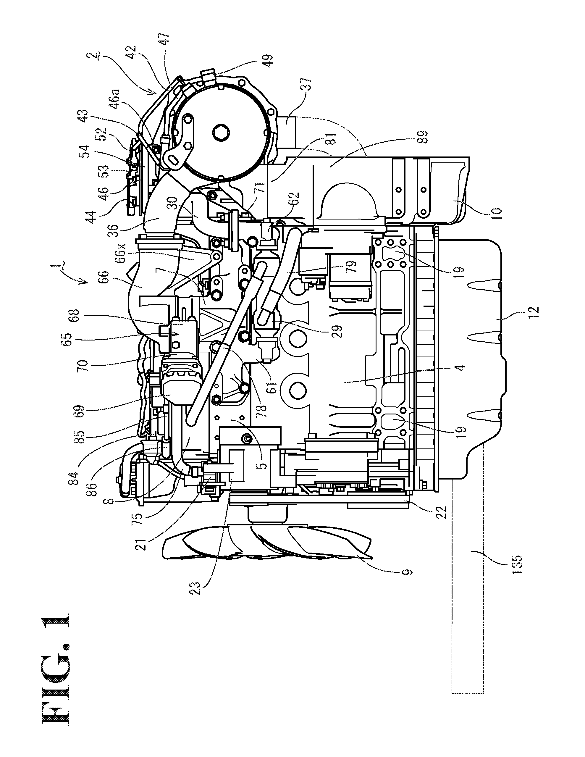
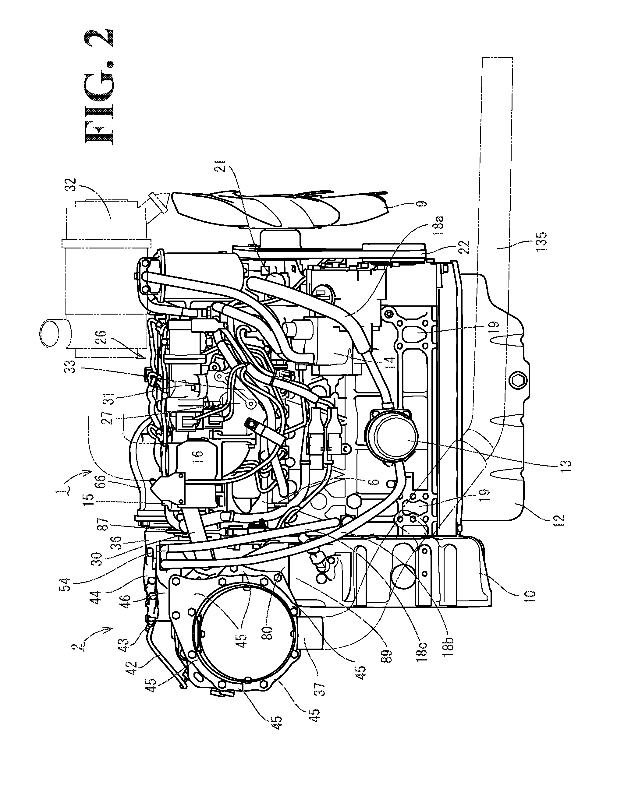
[0062]Hereinafter, an embodiment of an engine device according to the present invention and an embodiment of a work machine according to the present invention including the engine device will be described with reference to FIGS. 1 to 17. A stationary work machine will be given below as the embodiment of a work machine according to the present invention, and the details of the configuration of the stationary work machine will be described below.

[0063]First, a diesel engine 1, an embodiment of an engine device according to the present invention, will be described with reference to FIGS. 1 to 14. This diesel engine 1 is mounted in a work machine, such as a stationary work machine described below, and serves as a prime mover for the work machine. As described above, the diesel engine 1 includes an exhaust-gas purification device 2, and this exhaust-gas purification device 2 is coupled to the diesel engine 1 via an exhaust-gas throttle device 65. The exhaust-gas purification device 2 inc...


PUM


Abstract

An engine includes an exhaust-gas purification device. The exhaust-gas purification device purifies exhaust gas. The exhaust-gas purification device includes electrical components. The electrical components detect the states of the exhaust-gas purification device. The engine includes a cooling-water circulation mechanism for circulating cooling water for the engine. Further, a portion of the cooling water circulated by the cooling-water circulation mechanism cools the electrical components.

Description

CROSS-REFERENCE TO RELATED APPLICATIONS[0001]The present application is a continuation application of International Application No. PCT / JP2015 / 56659, filed Mar. 6, 2015, which claims priority to Japanese Patent Application No. 2014-59103, filed Mar. 20, 2014, Japanese Patent Application No. 2014-59112, filed Mar. 20, 2014, and Japanese Patent Application No. 2014-62475, filed Mar. 25, 2014. The contents of these applications are incorporated herein by reference in their entirety.BACKGROUND OF THE INVENTION[0002]The present invention relates to an engine device and a stationary work machine having the same mounted thereon.[0003]To date, technologies that allow an exhaust-gas purification device (a diesel particulate filter) to be disposed in an exhaust path for an engine to allow an oxidation catalyst, a soot filter, or any other similar assembly included in the exhaust-gas purification device to perform purification processing on exhaust gas discharged from the diesel engine have be...

Claims


Application Information

Patent Timeline
Patent Type & Authority Applications(United States)
IPC IPC(8): F01P3/20F01N13/18F01P5/02F01N13/00F01P7/02F01N3/023F01N3/10F01N11/00F01N13/10F02B63/04
CPCF01P3/20F01N2590/10F01N13/1805F01P5/02F02B63/04F01P7/02F01N3/023F01N3/103F01N11/00F01N13/0097F01N2260/024F01N2340/04F01N2560/06F01N2560/08F01N13/10F01N3/021F01N3/0231F01N3/106F01N3/2885F01N13/08F01N13/1855F01N2590/08Y02T10/40
Inventor MITSUDA, MASATAKAKUSAKA, HOKUTOYAMADA, MASAYUKITAGUCHI, ISAO
Owner YANMAR POWER TECHNOLOGY CO LTD
Why Eureka
Try Eureka