[0007]The present invention is based on the general idea of coating the tubular body with a
composite ceramic, which is based on nanoparticles. Such a coating may be embodied especially as a heat-insulating coating. For example, its
emissivity may be ≦0.5 at least in a predetermined temperature range. Provisions may be made for coating the tubular body with the coating consisting of
composite ceramic based on nanoparticles exclusively on an inside facing the exhaust gas. As a result, the
radiant heat transmission from the exhaust gas to the tubular body can be significantly reduced in case of a corresponding
emissivity. It is possible, as an alternative, to provide the tubular body with the coating consisting of composite
ceramic based on nanoparticles exclusively on an outside facing away from the exhaust gas. The
heat transmission from the tubular body into the environment, i.e., especially the heat
radiation, is significantly reduced hereby. Furthermore, it is also possible to provide the tubular body with a coating consisting of composite
ceramic based on nanoparticles both on its inside and on its outside in order to thus reduce, on the one hand, the
heat transmission from the exhaust gas to the tubular body and, on the other hand, the
heat transmission from the tubular body to the environment.
[0009]Various parameters of the composite
ceramic prepared on the basis of nanoparticles can be varied in a specific manner by selecting and composing the nanoparticles used. For example, it is thus possible to set the coefficient of
thermal expansion of the coating such that it is quasi equal to the coefficient of
thermal expansion of the tubular body. An especially intensive connection with long-term stability can be achieved as a result between the coating and the tubular body for the entire thermal range of the use of the tubular body or of the exhaust system. Furthermore, heat emission coefficients, so-called emissivities, can be set comparatively precisely. It is possible as a result, in particular, to significantly reduce the heat
radiation to the outside. Another special
advantage of such coatings is that it is sufficient to apply these as a comparatively
thin layer to the tubular body to achieve the desired heat insulating effect. Such a coating correspondingly requires hardly any installation space and does not lead, moreover, to any significant increase in the weight of the tubular body.
[0014]Another embodiment, in which the respective coating is provided with a temperature-dependent heat
emission coefficient, may be especially advantageous. For example, the tubular body can better adapt as a result in respect to its coatings to a predetermined operating state or
operating temperature range of the exhaust system.
[0016]The respective coating may have, in principle, essentially the same coefficient of thermal expansion as the tubular body. This leads to an especially high long-term stability as well as to constant properties over the entire temperature range.
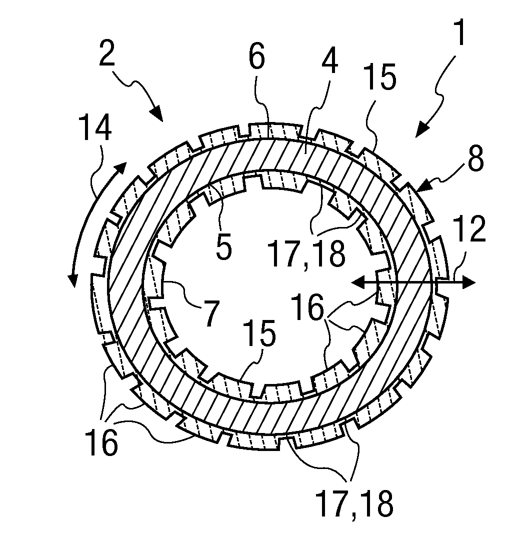
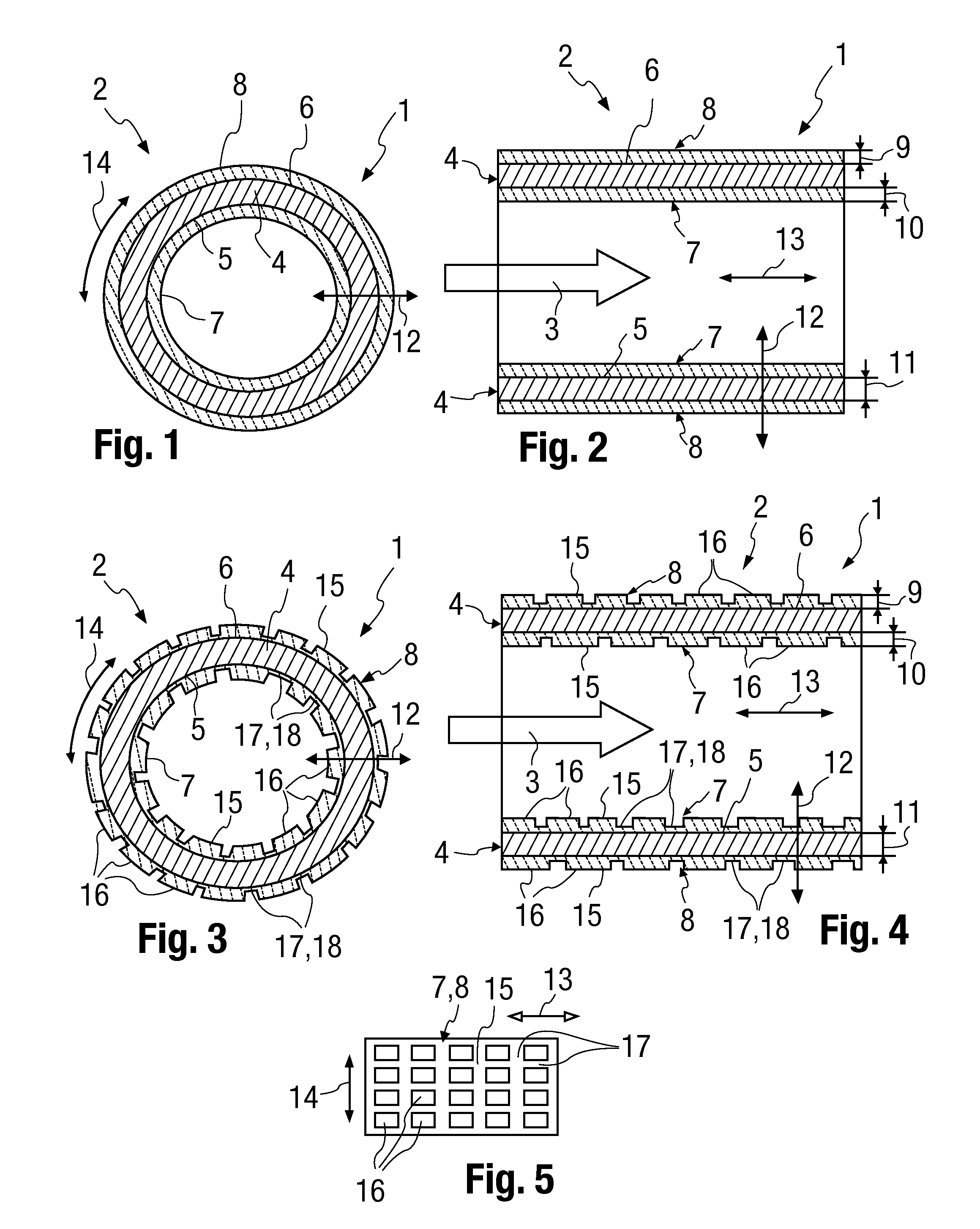
[0017]An alternative is an embodiment in which the respective coating specifically has a lower coefficient of thermal expansion than the tubular body. The respective coating is provided with a
microstructure in this embodiment, such that the respective coating comprises a plurality of individual coating sections, which are each firmly connected to the tubular body, but are mobile relative to one another with the thermal expansion of the tubular body. Such a
microstructure can be embodied, for example, by surface grooves or by cracks in the coating. In conjunction with the different thermal expansion of the coating, at least one temperature-
dependent parameter can be embodied by means of such a
microstructure. For example, the above-mentioned grooves or cracks are comparatively small or closed at low temperatures, as a result of which the respective coating has an increased effectiveness in terms of heat insulation. The individual coating sections move apart from each other at higher temperature because of the expansion of the tubular body, as a result of which said grooves or cracks become larger. The insulating properties of the coating become worse as a consequence. In other words, the heat insulation decreases with rising temperature, which increases the release of heat, and an overheating protection effect can thus be achieved as well.

