System and method for positioning an object

a positioning system and object technology, applied in the field of electron beam or ion beam system, can solve the problems of limited viewing space of electron beam and fib system, inferior arrangement of axes of motion, and limit the accuracy of measurement(s) that can be obtained, so as to achieve accurate and precise measurement of the position of the object carrier and precise control of the second stage

Inactive Publication Date: 2007-02-01
LEWIS GEORGE C +1
View PDF10 Cites 31 Cited by
  • Summary
  • Abstract
  • Description
  • Claims
  • Application Information

AI Technical Summary

Benefits of technology

[0008] The principles of the present invention address the aforementioned and other problems associated with the motion system described in reference to FIG. 1. In accordance with the principles of the present invention, a novel arrangement of laser interferometer elements and axes of motion permits accurate and p...

Problems solved by technology

The stacked arrangement in such a multi-axis motion system 2 limits accuracy of measurement(s) that can be obtained.
Electron beam and FIB systems have limited viewing space.
This problem is generally due to mechanical tolerances.
Sometimes it is due to an inferior arrangement of the axes of motion.
It is also a challeng...

Method used


Image

  • System and method for positioning an object
  • System and method for positioning an object
  • System and method for positioning an object

Examples


Embodiment Construction

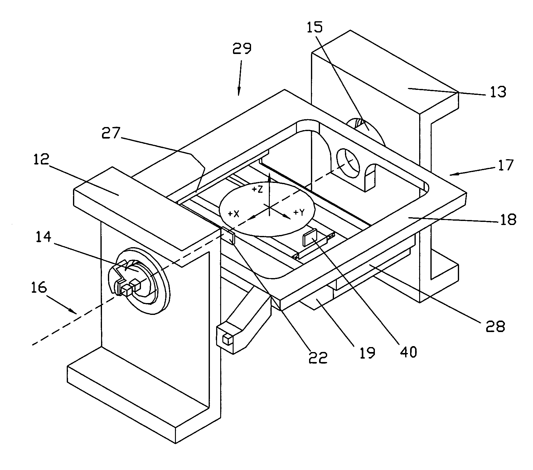
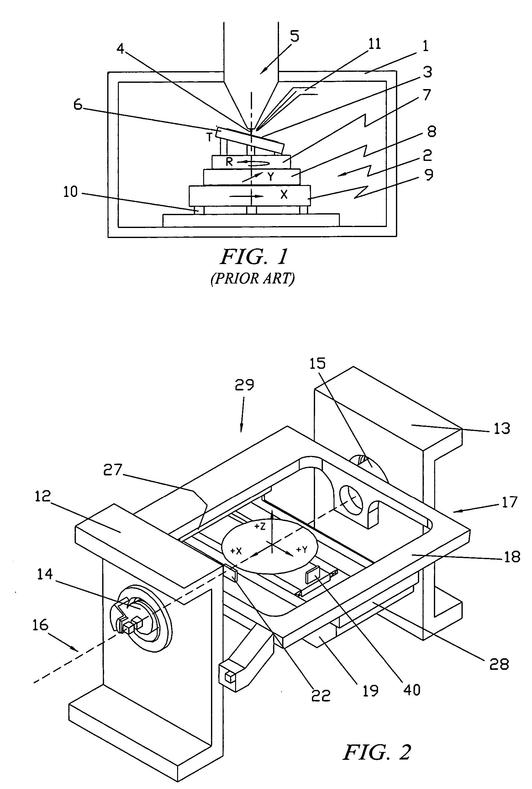
[0034]FIG. 2 is a diagram of a motion system 29 according to the principles of the present invention. A right structural support member 12 and a left structural support member 13 have within them a right rotational element 14 and a left rotational element 15, respectively. These two rotational elements 14 and 15 define one axis of rotation, the first (tilt) axis 16. The first axis 16 carries a first stage 17, which includes a first stage frame 18 attached to the rotational elements 14 and 15.

[0035] In a preferred embodiment, the first stage frame 18 is attached to inner races (not shown) of spindle ball bearings by means well known in the art. It should be understood that other designs, such as gas bearings, roller bearings, crossed flexures, or other low friction rotational elements, can be used. But, the use of spindle ball bearings has other advantages as explained below in reference to FIG. 15.

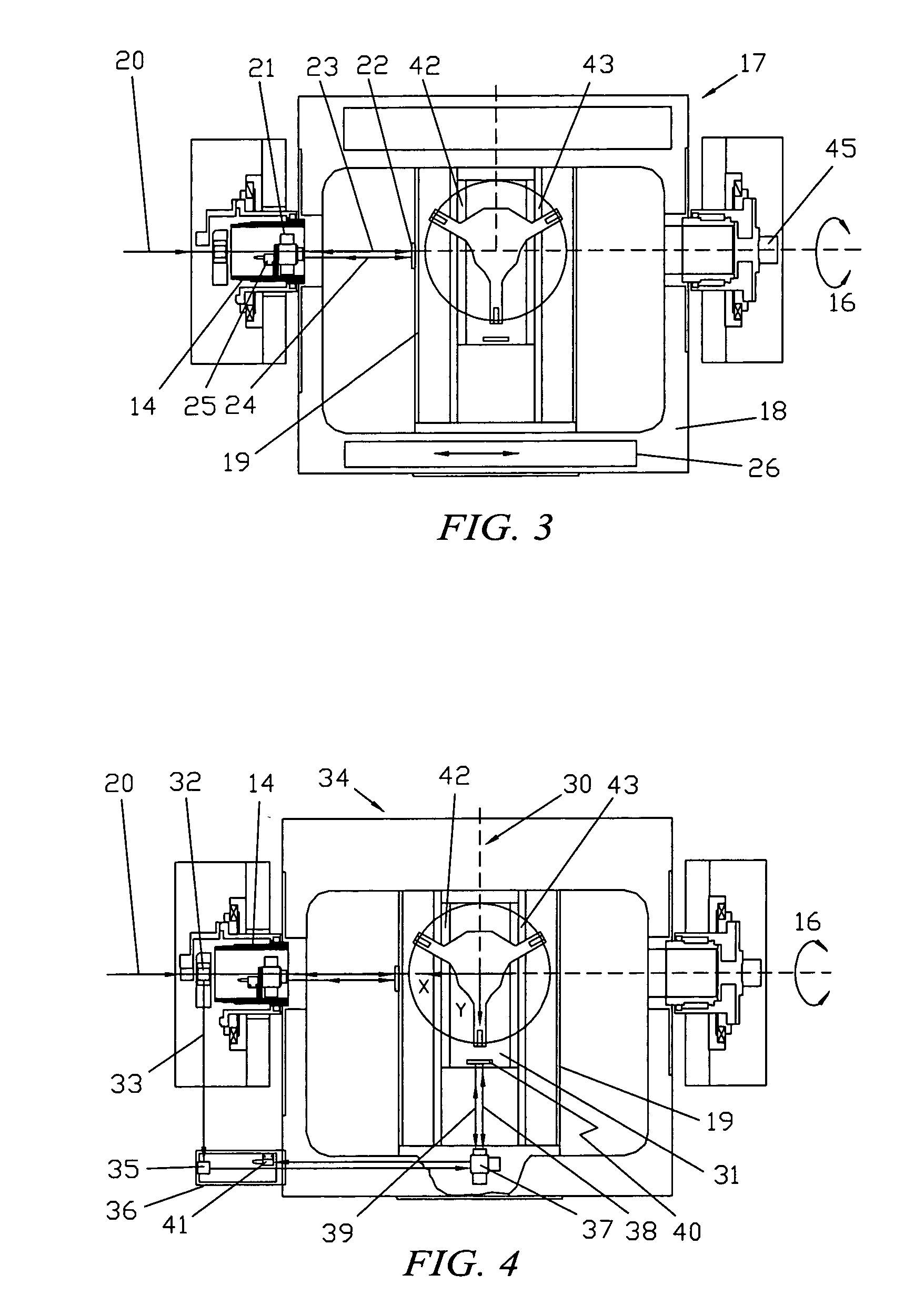
[0036] Referring briefly to FIG. 12, a first axis drive motor 45 is attached to the ...


PUM


Abstract

A motion system includes a first stage that is configured to rotate about a first axis and a second stage coupled to the first stage that includes an object carrier adapted to position an object in at least one other axis. The motion system has a novel arrangement of laser interferometer elements and axes of motion. The arrangement permits accurate and precise measurement of a position of the object carrier in up to three (or more) axes of motion even as the first stage of the motion system is tilted through relatively large angles. The novel arrangement of the axes of motion also enables very precise control of the position of the object carrier even at high tilt angles.

Description

BACKGROUND OF THE INVENTION [0001]FIG. 1 shows a typical electron beam or ion beam system. A vacuum chamber 1 contains a multi-axis motion system 2 which is used to position an object 3, such as a semiconductor wafer, under a beam 4 so that one or more sites of interest on the object 3 may be examined or processed. A column 5 on top of the vacuum chamber 1 provides an electron beam or ion beam. Generally, an electron beam is used to scan, observe, and measure features at sites of interest on the object 3. Focused ion beams (FIB) may be used to observe and repair features. Electron, laser, or ion beams can be used to control processes, such as removal or deposition of material(s), at sites of interest on the object 3. In some designs, two or more columns are used on one vacuum chamber, such as an electron beam system for observing defects and a separate FIB column for repairing defects. [0002] A common arrangement in such motion systems is to have a tilting stage 6 on top of a rotati...

Claims


Application Information

Patent Timeline
IPC IPC(8): G21K5/10
CPCH01J2237/20292H01J37/20
Inventor LEWIS, GEORGE C.KROKAR, ZELIMIR
Owner LEWIS GEORGE C
Why Eureka
Try Eureka