
Semiconductor device

a semiconductor element and device technology, applied in the field of semiconductor devices, can solve problems such as impairment of the characteristics of semiconductor elements

Inactive Publication Date: 2007-02-01
SEIKO EPSON CORP
View PDF19 Cites 2 Cited by
  • Summary
  • Abstract
  • Description
  • Claims
  • Application Information

AI Technical Summary

Benefits of technology

[0015] The invention may provide a semiconductor device which allows formation of an element under an electrode pad and exhibits high reliability.
[0003] When a semiconductor element such as a MIS transistor is disposed under a pad, the characteristics of the semiconductor element may be impaired due to stress during bonding. Therefore, a pad formation region and a semiconductor element formation region are separately provided in a semiconductor chip when viewed from the top side. In recent years, along with a reduction in size and an increase in degree of integration of a semiconductor chip, disposition of a semiconductor element under a pad has been demanded. JP-A-11-307724 discloses an example of such a technology. JP-A-11-307724 discloses an island-like buffer layer formed under a bonding pad.
[0015] The invention may provide a semiconductor device which allows formation of an element under an electrode pad and exhibits high reliability.

Problems solved by technology

When a semiconductor element such as a MIS transistor is disposed under a pad, the characteristics of the semiconductor element may be impaired due to stress during bonding.

Method used


Image

  • Semiconductor device
  • Semiconductor device
  • Semiconductor device

Examples


Embodiment Construction

[0015] The invention may provide a semiconductor device which allows formation of an element under an electrode pad and exhibits high reliability.

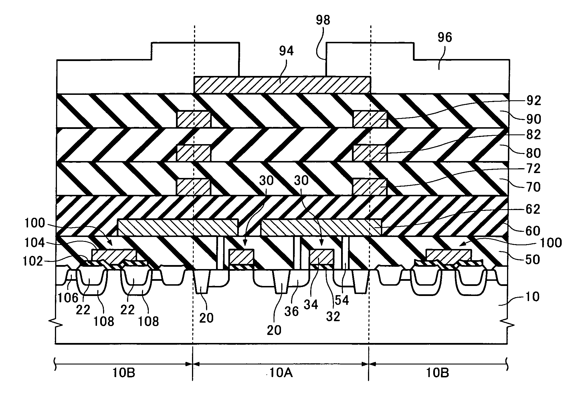
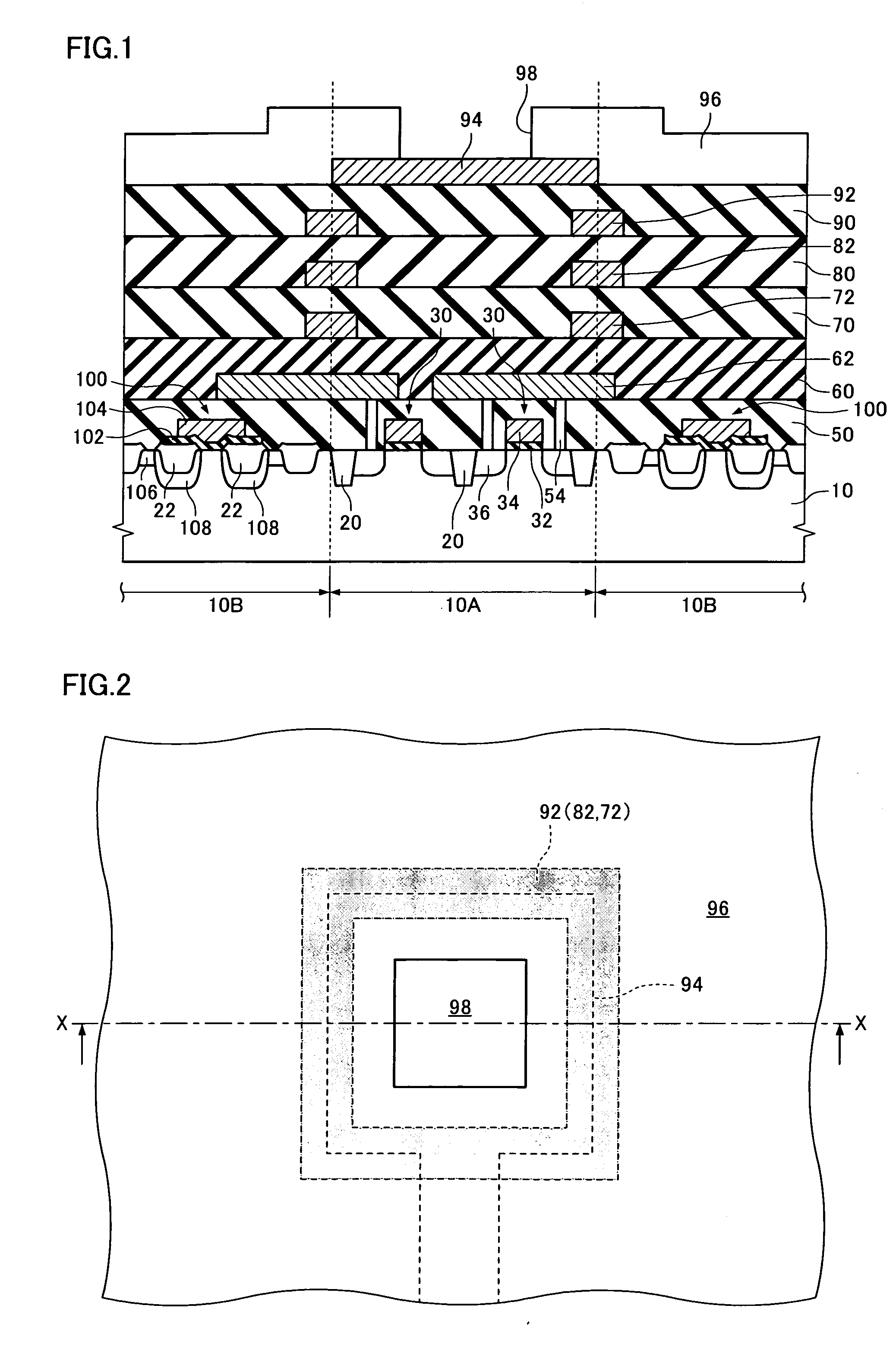
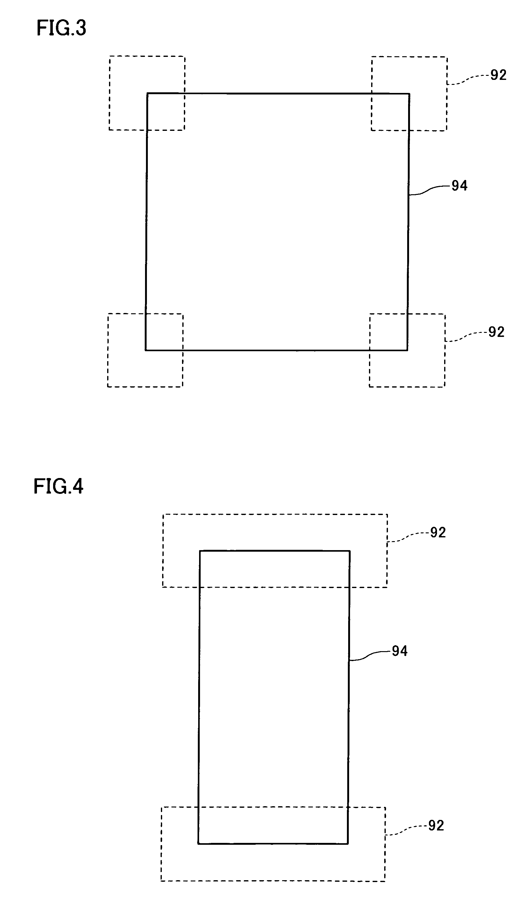
[0016] (1) According to one embodiment of the invention, there is provided a semiconductor device comprising: [0017] a semiconductor layer; [0018] an interlayer dielectric formed on the semiconductor layer; [0019] a buffer layer formed on the interlayer dielectric; and [0020] an electrode pad formed on the interlayer dielectric, [0021] the buffer layer being formed to be covered by an edge portion of at least part of the electrode pad when viewed from a top side.

[0022] In the region near the edge of the electrode pad, stress occurs due to the electrode pad. Therefore, cracks tend to occur in the interlayer dielectric in the region near the edge of the electrode pad. For example, when a semiconductor element such as a MIS transistor has been formed in the region near the edge of the electrode pad, the characteristics of the MIS transistor...


PUM


Abstract

A semiconductor device having: a semiconductor layer; an interlayer dielectric formed on the semiconductor layer; a buffer layer formed on the interlayer dielectric; and an electrode pad formed on the interlayer dielectric, the buffer layer being formed to be covered by an edge portion of at least part of the electrode pad when viewed from a top side.

Description

[0001] Japanese Patent Application No. 2005-218904, filed on Jul. 28, 2005, is hereby incorporated by reference in its entirety. BACKGROUND OF THE INVENTION [0002] The present invention relates to a semiconductor device. [0003] When a semiconductor element such as a MIS transistor is disposed under a pad, the characteristics of the semiconductor element may be impaired due to stress during bonding. Therefore, a pad formation region and a semiconductor element formation region are separately provided in a semiconductor chip when viewed from the top side. In recent years, along with a reduction in size and an increase in degree of integration of a semiconductor chip, disposition of a semiconductor element under a pad has been demanded. JP-A-11-307724 discloses an example of such a technology. JP-A-11-307724 discloses an island-like buffer layer formed under a bonding pad. SUMMARY [0004] According to one aspect of the invention, there is provided a semiconductor device comprising: [000...

Claims


Application Information

Patent Timeline
IPC IPC(8): H01L29/76
CPCH01L24/03H01L2224/05554H01L24/06H01L29/78H01L2224/05599H01L2224/05624H01L2224/05647H01L2924/01004H01L2924/01005H01L2924/01013H01L2924/01014H01L2924/01015H01L2924/01029H01L2924/01032H01L2924/01033H01L2924/01079H01L2924/01082H01L2924/19043H01L24/05H01L2224/02166H01L2924/00014H01L2924/01006H01L27/04H01L21/3205H01L21/822
Inventor SHINDO, AKINORI
Owner SEIKO EPSON CORP
Learn More