Tire belt machine

a belt machine and belt technology, applied in dough shaping, other domestic objects, manufacturing tools, etc., can solve the problems of belt unsuitability for intended use, variability in the width of fiber reinforced strips, and difficulty in material handling

Active Publication Date: 2007-02-01
STEELASTIC COMPANY L L C THE
View PDF28 Cites 12 Cited by
  • Summary
  • Abstract
  • Description
  • Claims
  • Application Information

AI Technical Summary

Benefits of technology

[0008] It is an object of the present invention

Problems solved by technology

Because the process involves uncured elastomeric material, handling of the material is difficult.
This difficulty stems largely from the variability in width of the fiber reinforced strip.
Difficulties in aligning adjacent sheets on the belt conveyor often result in poor splices making the belt unsuitable for its intended use.
These inaccuracies are of

Method used


Image

  • Tire belt machine
  • Tire belt machine
  • Tire belt machine

Examples


Embodiment Construction

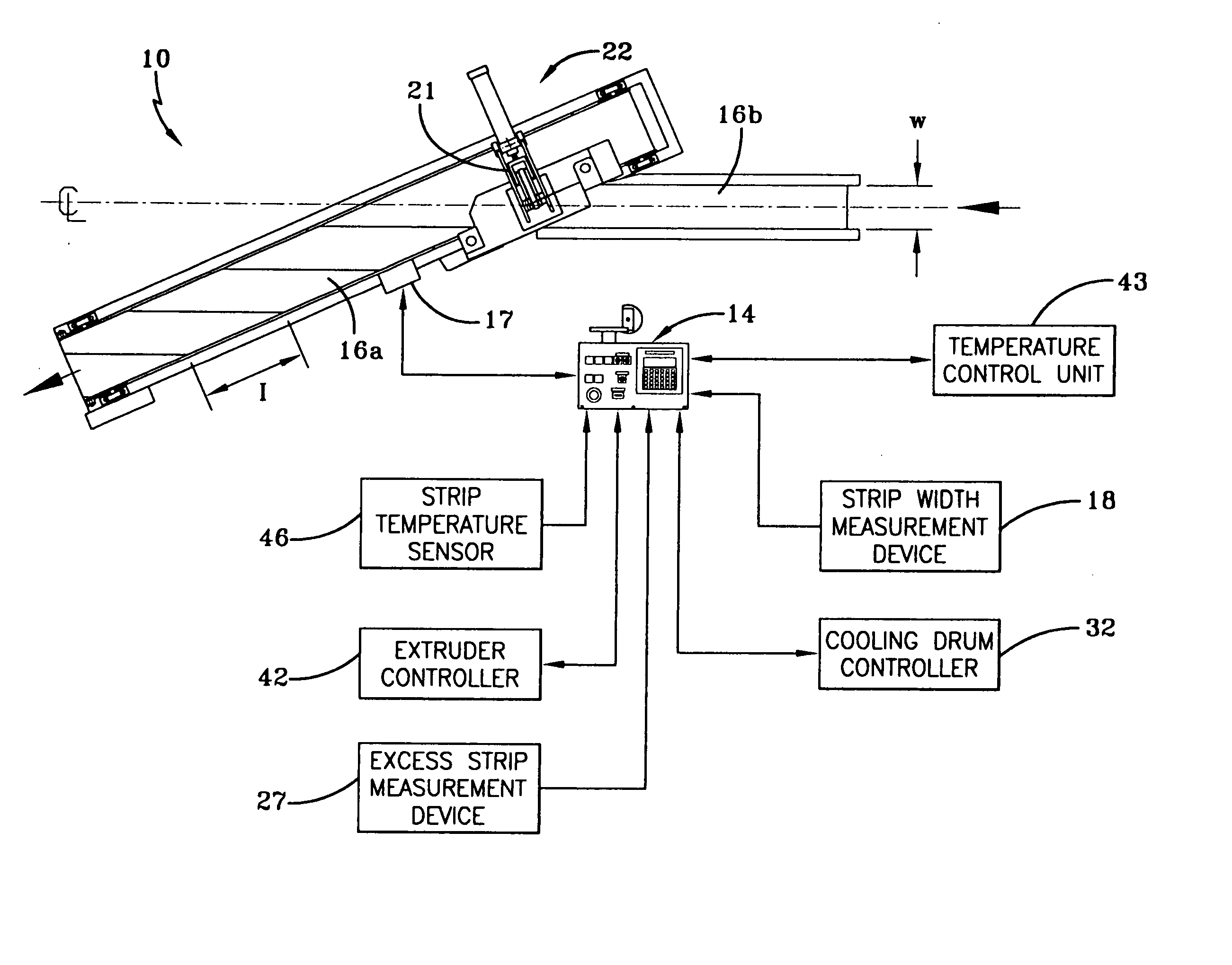
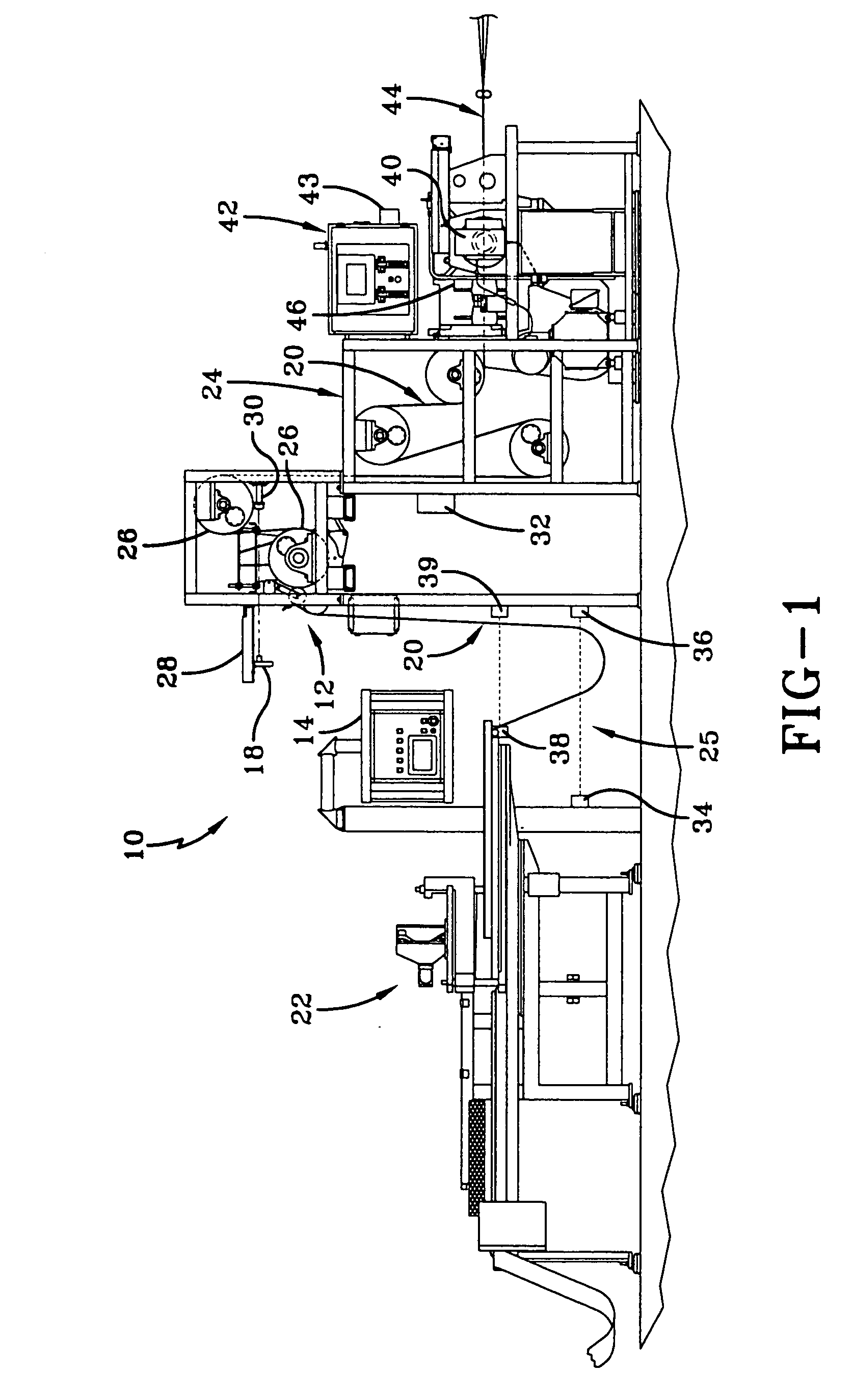
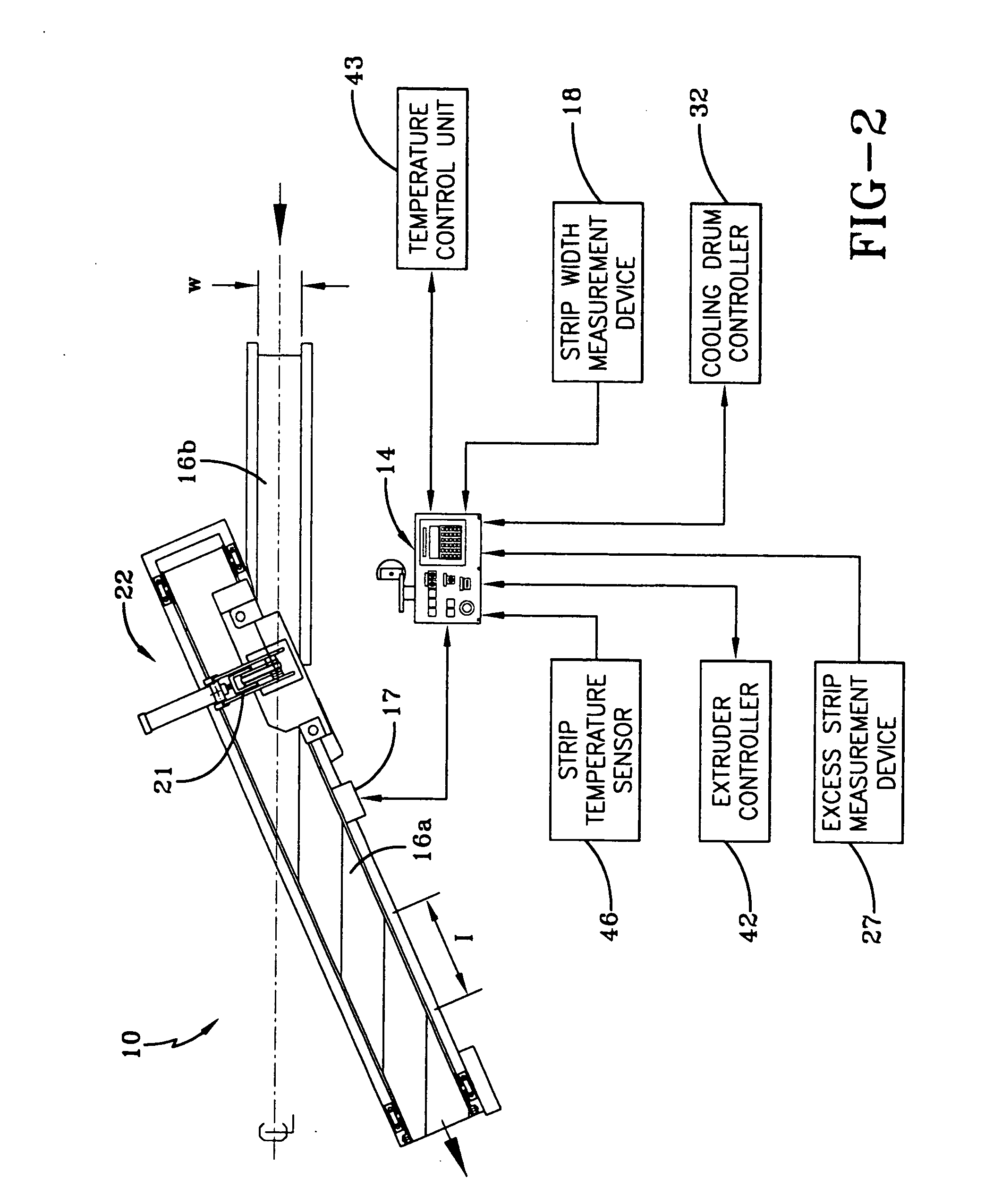
[0021] A tire belt making system according to the concepts of the present invention is generally indicated by the numeral 10 in the drawings. The belt making system employs a central control unit 14 that electronically controls various systems. These systems could include a strip width measurement and adjustment system, a strip tracking system, electronic extruder control, and a strip temperature sensing system. Each of these elements is in communication with central control unit 14. Central control unit 14 gathers information from the various systems and modifies system parameters when necessary to help minimize operator supervision and adjustment while ensuring maximum production speed.

[0022] According to one aspect of the present invention, system 10 includes a strip width monitoring system, generally indicated by the numeral 12. This system monitors the width W of the fiber reinforced strip and makes appropriate parameter adjustments to ensure a quality final product. A strip w...


PUM

PropertyMeasurementUnit
Temperatureaaaaaaaaaa
Lengthaaaaaaaaaa
Pressureaaaaaaaaaa

Abstract

A method of controlling a tire belt machine having a cutting station that receives a strip of material cuts it into plural lengths that are spliced together on a belt conveyor, the method including establishing a belt conveyor index distance; receiving signals representing a width of the strip entering a cutting station; and automatically adjusting the belt conveyor index distance based on the strip's width such that uniform splice characteristics are attained.

Description

RELATED PATENT APPLICATIONS [0001] None. TECHNICAL FIELD [0002] In general, the present invention relates to a tire belt machine. More particularly, the present invention relates to a tire belt machine having improved control that simultaneously monitors and adapts all aspects of the belt making process. BACKGROUND OF THE INVENTION [0003] Tire belt formation is a well known practice that involves pulling multiple cords through an extrusion die. The extruder heats elastomeric material and coats the cords traveling through the die. Cooling drums adjacent to the extruder act both to pull the cords through the die and cool the fiber reinforced material before the cutting and splicing phase of production. After traveling through the cooling drums, the fiber reinforced material is allowed to hang with some slack in order to remove some residual forces. The fiber reinforced material is then drawn onto a cutting station. The cutting station includes a strip vacuum transfer, a cutter and a b...

Claims


Application Information

Patent Timeline
IPC IPC(8): B29C47/92B29D29/00B29C47/08B29C48/92
CPCB29D30/38Y10T156/13B29D2030/427B29D2030/428B29D2030/4406B29C65/7832B29C66/1122B29C66/435B29C66/71B29C66/73752B29C66/72141Y10S156/907B29D30/42B29C47/92B29K2021/00B29C48/92B29C2948/92209B29C2948/92704B29C2948/92133B29C2948/92438B29C2948/92447B29C2948/92514B29C2948/9259B29C2948/92638B29C2948/92885B29C2948/92895B29C2948/92923B29C2948/92942
Inventor BULL, JEFFREY F.SMITH, EVAN
Owner STEELASTIC COMPANY L L C THE
Why Eureka
Try Eureka