Electronically commutated motor (ECM) and method of controlling an ecm

a technology of electronic commutation and motor, which is applied in the direction of commutation monitoring, synchronous motor starters, dynamo-electric machines, etc., can solve the problems of damage to or destruction of associated power stages

Inactive Publication Date: 2007-02-01
EBM PAPST ST GEORGEN & -
View PDF6 Cites 64 Cited by
  • Summary
  • Abstract
  • Description
  • Claims
  • Application Information

AI Technical Summary

Benefits of technology

[0005] The invention is based on the recognition that a short circuit occurring in an ECM produces an overcurrent at a power stage associated with the ECM. An overcurrent of this kind can be detected with suitable overcurrent measuring elements, and a shutoff of the power stage can be produced in reaction to the detection of the overcurrent. By means of a shutoff of the power stage, the motor electronics of the ECM can be protected from damage or destruction by the overcurrent. The invention is not, however, limited to a specific type of motor, but rather is suitable for electric motors of any kind.
[0006] The object of the present invention is achieved in particular by means of an electronically commutated motor having an overcurrent detector and a holding element, responsive to the overcurrent detector, for sending a shutoff signal to the power stage. By means of the shutoff of the power stage, the power stage and the motor are protected from damage or destruction by the overcurrent.

Problems solved by technology

In an electronically commutated motor (ECM), a short circuit occurring during operation of the motor can result in damage to or destruction of an associated power stage.

Method used


Image

  • Electronically commutated motor (ECM) and method of controlling an ecm
  • Electronically commutated motor (ECM) and method of controlling an ecm
  • Electronically commutated motor (ECM) and method of controlling an ecm

Examples


Embodiment Construction

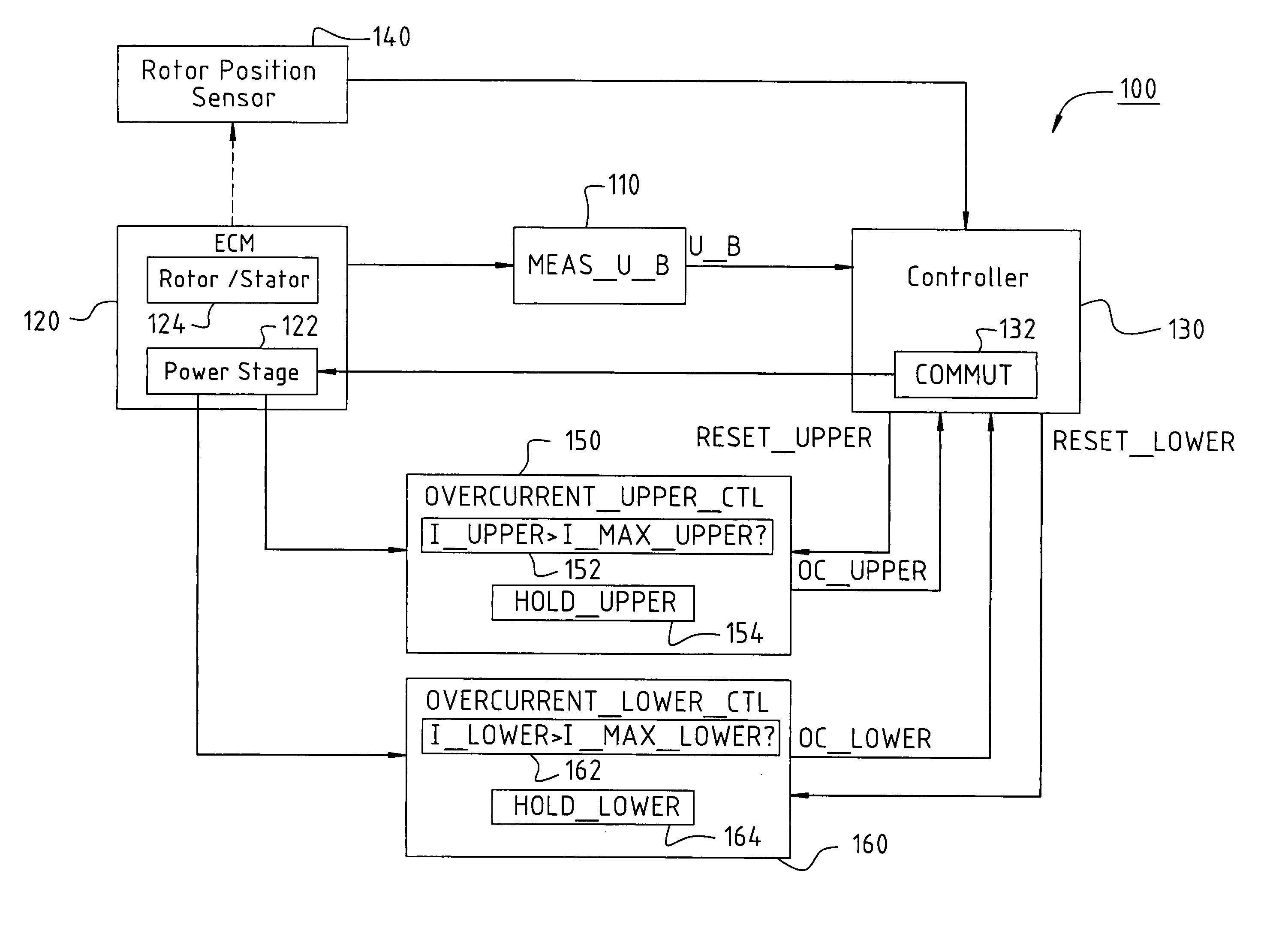
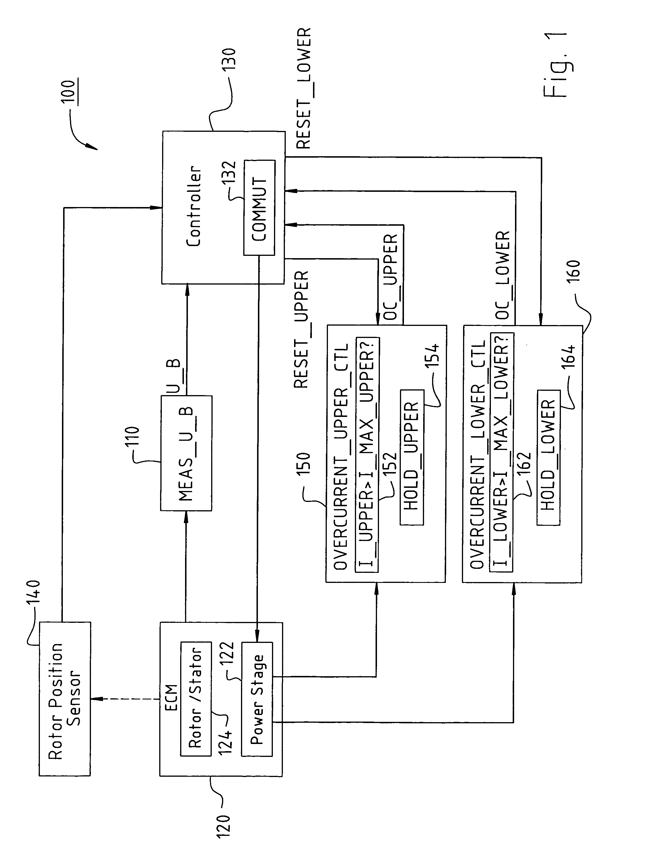
[0016]FIG. 1 is a block diagram illustrating, in principle, the functioning of an apparatus 100 according to the present invention for operating an ECM 120 having a short-circuit shutoff system. Apparatus 100 is configured, on the one hand, for detection of an overcurrent occurring as a result of a short circuit in ECM 120. On the other hand, apparatus 100 is configured to shut off ECM 120 in reaction to the detection of the overcurrent, in order to prevent damage to or destruction of ECM 120 by the overcurrent.

[0017] According to an embodiment of the present invention, apparatus 100 encompasses an ECM 120 with a rotor / stator arrangement 124 (Rotor / Stator) having a rotor and at least one stator phase. A power stage 122, for influencing the motor current in the at least one stator phase, is associated with ECM 120. Apparatus 100 furthermore encompasses a controller 130 that is connected to ECM 120. Controller 130 encompasses a commutation controller 132 (COMMUT), and is connected at...


PUM


Abstract

An electronically commutated motor comprises a rotor (208); a stator (201) electromagnetically interacting with the rotor (208), which stator is formed with a stator winding (202, 204, 206); a power stage (122) controlling the currents flowing in the stator winding (202, 204, 206) during operation; at least one current measuring element (242, 244) for sensing a measured value for the currents (I_UPPER, I_LOWER) flowing in the power stage, and an overcurrent measuring element (152, 162) for evaluating an associated measured value and for sensing a current whose absolute value exceeds a predetermined limit value (I_MAX_UPPER, I_MAX_LOWER); a holding element (154, 164) associated with the overcurrent measuring element (152, 162), configured, when an overcurrent occurs in the associated current measuring element (242, 244), to generate an overcurrent signal (OC_UPPER, OC_LOWER), to store the signal, and to deliver a signal to the power stage (122).

Description

CROSS REFERENCE [0001] This application claims priority from German application DE 10 2005 036 651.1, filed 28 Jul. 2005, the entire content of which is hereby incorporated by reference. FIELD OF THE INVENTION [0002] The invention relates to an electronically commutated motor and a method of controlling an electronically commutated motor. BACKGROUND [0003] In an electronically commutated motor (ECM), a short circuit occurring during operation of the motor can result in damage to or destruction of an associated power stage. To prevent such damage or destruction, the associated power stage must be protected against possible error states, in particular against short circuit. It is desirable in this context to protect the associated power stage and the ECM, by means of a suitable protective circuit, against a short circuit of the ECM's phases, a short circuit to ground, a short circuit with respect to a corresponding supply voltage of the ECM, a winding short circuit, and / or a power sta...

Claims


Application Information

Patent Timeline
Patent Type & Authority Applications(United States)
IPC IPC(8): H02P7/00
CPCH02H7/0838H02P6/002H02P29/021H02P6/12H02P6/28H02P29/0241
Inventor HAHN, ALEXANDERSCHMID, HARALDKISCH, MICHAEL
Owner EBM PAPST ST GEORGEN & -
Why Eureka
Try Eureka