Measuring device and measuring method for determining distance and/or position

a technology of measuring device and distance, applied in the direction of distance measurement, instruments, using reradiation, etc., can solve the problems of inability to accurately parallel aligned beams, cannot be taken easily, so as to achieve low divergence and simplify the control and adjustment of the device

Inactive Publication Date: 2007-02-01
ANDROTEC GMBH
View PDF31 Cites 33 Cited by
  • Summary
  • Abstract
  • Description
  • Claims
  • Application Information

AI Technical Summary

Benefits of technology

[0020] It is possible to use a set of different beams e.g. ultrasonic beams. It is however preferred, if light beams are emitted as signal beams, as this especially simplifies the control and adjustment of the device. The use of laser light beams is particularly preferable, since laser light sources are available, are inexpensive and emit with only low divergence.

Problems solved by technology

Systems of this type are already used in industrial applications, they are however expensive, as the running times of the light pulses are short and a gating electronic operating at high frequency operating is required, which must respond accordingly quickly.
Hereby measurements can be facilitated, however they cannot be taken easily.
This measurement principle however is limited neither exclusively to laser light, nor to only two, nor to accurately parallel aligned beams.

Method used


Image

  • Measuring device and measuring method for determining distance and/or position
  • Measuring device and measuring method for determining distance and/or position
  • Measuring device and measuring method for determining distance and/or position

Examples


Embodiment Construction

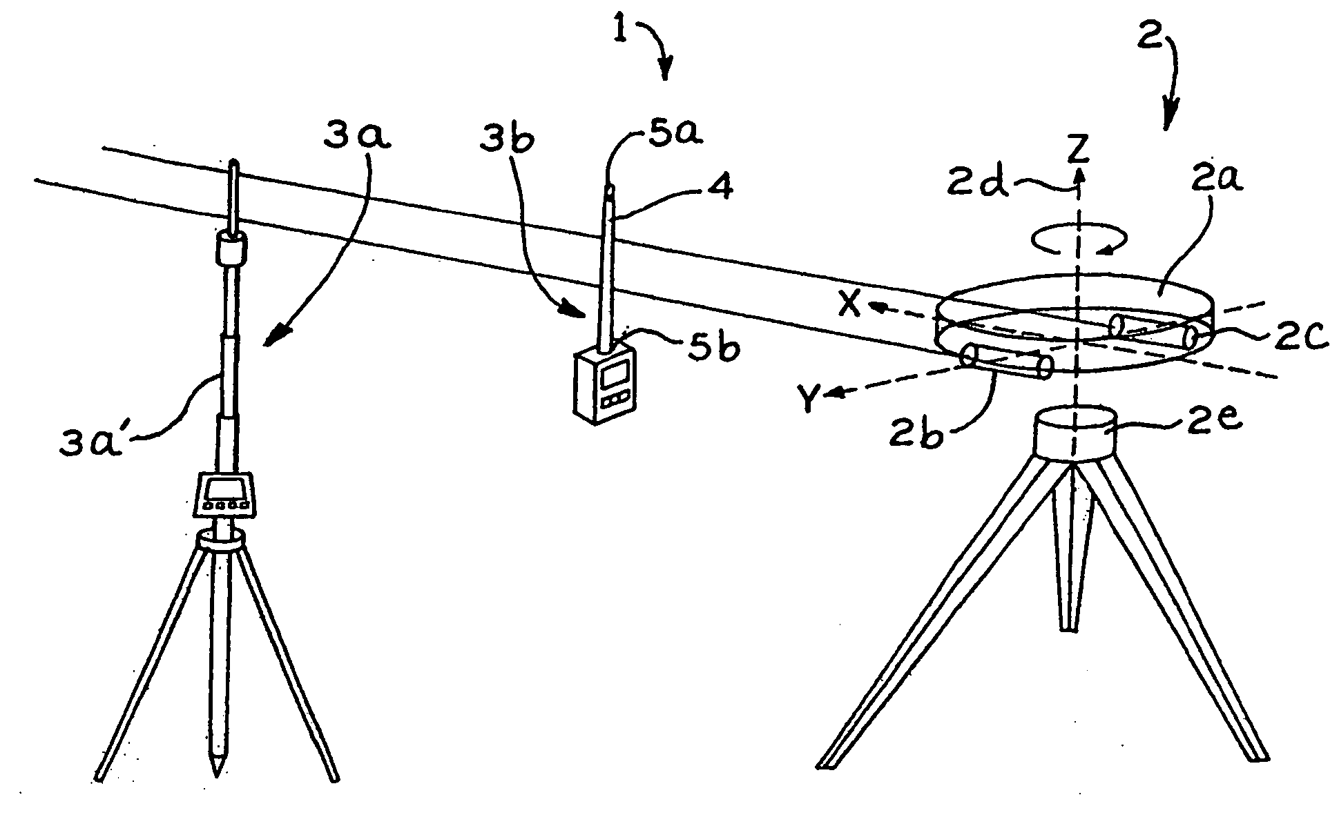
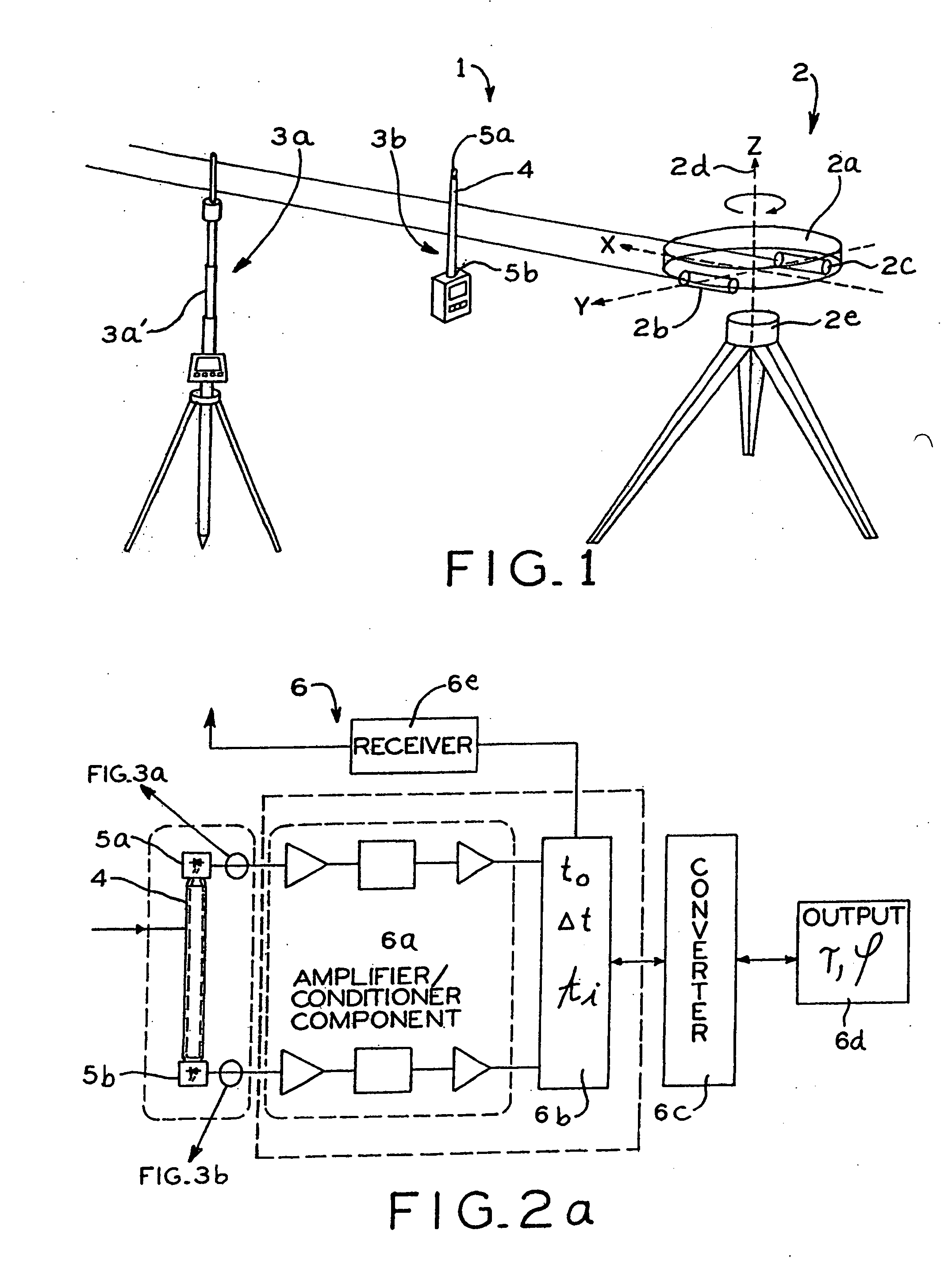
[0046] According to FIG. 1 a measuring device for local position determination, generally denoted with 1, comprises a signal generator 2 and several signal receivers 3a, 3b located at a measurable distance from said signal generator.

[0047] The signal generator 2 comprises a platform 2a, on which two laser light sources 2b, 2c are located for the emission of generally parallel signal beams. The lasers 2b, 2c can be rotated around a rotation axis 2d together with the platform 2a by a drive unit 2e with controlled, constant speed; said rotation axis runs generally vertically and is normal to the generally parallel laser beams.

[0048] A radio signal generator, which beams a signal referred to the point in time t0 of a zero-angle passage is not shown.

[0049] The first signal receiver 3a is a stationary signal receiver, while the second shown signal receiver 3b is a handheld signal receiver. Generally it is possible to use practically as many receivers at the same time as desired. The tw...


PUM


Abstract

A measuring device is provided with a signal generator and a signal receiver, which is located at a measurable distance from the signal generator. The signal generator is designed for the emission of at least two signal beams covering in given relationship to each other an area and the signal receiver is designed for the time-resolved reception of the signal beams in such a manner that the generator-receiver distance can be determined from the time signature of the signal beam reception.

Description

CROSS-REFERENCE TO RELATED APPLICATIONS [0001] The present application is a divisional application of application Ser. No. 10 / 343,538, titled “MEASURING DEVICE AND MEASURING METHOD FOR DETERMINING DISTANCE AND / OR POSITION,” filed on Jan. 31, 2003, now U.S. Pat. No. ______; which claims priority to PCT patent application No. PCT / EP01 / 08841, filed on Mar. 7, 2001; which claims priority to German patent application No. 100 59 240.6, filed on Nov. 29, 2000 and German patent application No. 100 37 853.6, filed on Aug. 1, 2000.BACKGROUND [0002] (1) Field of the Invention [0003] The present invention relates to the characterizing clauses of the independent claims. With these the invention generally deals with determining distances and / or positions. [0004] (2) Description of Related Art [0005] It is frequently necessary to be able to measure comparatively short distances in the range of several centimeters up to several hundred meters fast and very precise. Applications for this are for exa...

Claims


Application Information

Patent Timeline
Patent Type & Authority Applications(United States)
IPC IPC(8): G01C1/00G01C3/08G01C3/06G01B11/03G01B11/14G01C15/00G01S1/70G01S5/16G01S11/12
CPCG01C15/002G01S11/12G01S5/16G01S1/70G01C15/006G01S1/7038
Inventor ESSLING, MIRKOKASPER, MICHAELJOERG, KLAUS-WERNER
Owner ANDROTEC GMBH
Why Eureka
Try Eureka