Method and arrangement for the plasma-based generation of intensive short-wavelength radiation
a plasma-based and short-wavelength radiation technology, applied in the direction of x-ray tubes with very high current, radiation therapy, particle separator tubes, etc., can solve the problems of not being able to generate individual droplets under the process conditions, not being able to use xenon to generate individual droplets, and not being able to achieve the effect of reducing the emission of debris
- Summary
- Abstract
- Description
- Claims
- Application Information
AI Technical Summary
Benefits of technology
Problems solved by technology
Method used
Image
Examples
example 1
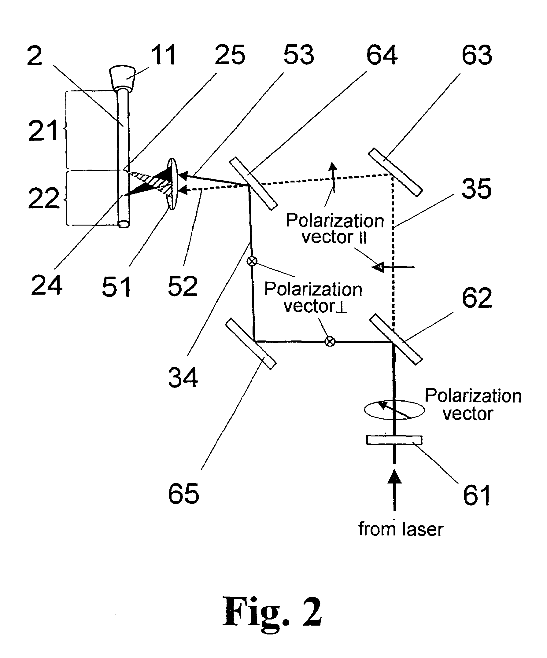
[0063]FIG. 3 is based on the diagram in FIG. 2 in that a polarized laser beam enters a beam guiding device 6, where it is converted by a half-wave plate 61 into a laser beam with nonvanishing orthogonal polarization components and is divided by means of a polarizing beam splitter 62 into different portions with polarization vectors ∥ and ⊥, respectively, that are parallel to or perpendicular to the drawing plane.
[0064]The laser beam with the parallel polarization vector ∥ arrives at the focusing lens 51 via a deflecting mirror 63 and a polarizing splitter 64 for this polarization direction located in the passing direction.
[0065]The laser beam with the perpendicular polarization vector ⊥ is directed by a tilting mirror 65 to a retroreflector 66 which reflects in parallel the beam deflected by the tilting mirror 65 and directs it to the polarizing splitter 64. The beam path along the tilting mirror 65 and the retroreflector 66 to the splitter 64 is an optical delay element 72 by which...
example 2
[0067]In the variant according to FIG. 4, the excitation laser beam 34 and dividing laser beam 35 are generated in two triggered lasers, laser A and laser B. The trigger unit 71 provided for this purpose normally triggers both lasers A and B simultaneously so that a delay element, which is realized in this case as an optical delay element 72 as in FIG. 3, is required for adjusting a time shift of the laser pulses. However, controlling by means of offset trigger pulses from the trigger unit 71 is also possible.
[0068]In this example and in all of the following examples, the portions 22 that are divided (not necessarily completely) from the continuous target jet 21 are generated in that the beam bundles 52 and 53 focused by the lasers A and B are focused on different locations (located one after the other along the target axis 23) which—assuming a target diameter of 20 μm—lie at a distance from one another of some 10 μm to several millimeters or in special cases (as is described later ...
example 3
[0071]In the arrangement shown in FIG. 5, two lasers A and B which are polarized linearly orthogonal to one another are combined by a polarizing splitter 64. The beam bundles 52 and 53 striking the focusing lens 51 are tilted slightly with respect to one another. The inclination of the beam axis directed to the splitter 64 is adjusted by the tilting mirror 65. As is described with reference to FIG. 4, a time delay of the pulses of the two lasers A and B, which is again optional, is realized by optical means by an additional retroreflector 66. In this example, the adjustment of the pulse delay of laser A is again carried out by means of a movable retroreflector 65, but could be realized alternatively in the same way in the beam path of laser B.
[0072]When using two lasers A and B with different wavelengths, the beam splitter 64—in contrast to the principle shown in FIG. 5—can also be realized as an edge filter (dichroic mirror) for combining the two laser beams with a slight tilt rela...
PUM
| Property | Measurement | Unit |
|---|---|---|
| repetition frequencies | aaaaa | aaaaa |
| wavelength | aaaaa | aaaaa |
| diameter | aaaaa | aaaaa |
Abstract
Description
Claims
Application Information
 - R&D
- Intellectual Property
- Life Sciences
- Materials
- Tech Scout
- Unparalleled Data Quality
- Higher Quality Content
- 60% Fewer Hallucinations
Browse by: Latest US Patents, China's latest patents, Technical Efficacy Thesaurus, Application Domain, Technology Topic, Popular Technical Reports.
© 2025 PatSnap. All rights reserved.Legal|Privacy policy|Modern Slavery Act Transparency Statement|Sitemap|About US| Contact US: help@patsnap.com


