Wide angle lens system and camera

a wide angle lens and wide angle technology, applied in the field of wide angle lens systems and cameras, can solve the problems of not being able to disclose effective means, unable to correct light beam aberration, and unable to etc., and achieve excellent image forming performan

Active Publication Date: 2007-02-01
MONUMENT PEAK VENTURES LLC
View PDF3 Cites 12 Cited by
  • Summary
  • Abstract
  • Description
  • Claims
  • Application Information

AI Technical Summary

Benefits of technology

[0022] According to the present invention, it is possible to provide a wide angle lens system configured to obtain excellent image forming performance even in a half field angle region of 40 degrees to 50 degrees.

Problems solved by technology

Therefore, Japanese Patent Laid-Open Publication No. 2004-53993 or Japanese Patent Laid-Open Publication No. 2003-302575, do not disclose effective means for correcting various aberrations such as a coma aberration outside an optical axis which becomes a problem when configuring a super wide angle lens system having a half field angle of 40 degrees to 50 degrees.
Therefore, correction of an aberration of a light beam which enters from a wide field angle is difficult when the fixed focus lens system disclosed in Japanese Patent Laid-Open Publication No. 2003-98430 is used to constitute a super wide angle lens system, and hence excellent image forming performance is hardly obtained.
However, in the case of the light path bending member disclosed in Japanese Patent Laid-Open Publication No. 2000-292692, manufacture of an optical element unit is difficult compared with a regular prism whose light ray transmitting surfaces or reflecting surfaces are all flat surfaces.
Further, since optical axis matching when incorporating such an optical element in an optical system is also very difficult, stably obtaining high performance is difficult in manufacture.
Furthermore, a half field angle of the lens system disclosed in Japanese Patent Laid-Open Publication No. 2003-98430 or Japanese Patent Laid-Open Publication No. 2000-292692 is approximately 30 degrees to 36 degrees, and these references do not disclose effective means for correcting various aberrations such as a coma aberration outside an optical axis which becomes a problem when constituting a super wide angle lens system whose half field angle is 40 degrees to 50 degrees.

Method used


Image

  • Wide angle lens system and camera
  • Wide angle lens system and camera
  • Wide angle lens system and camera

Examples


first embodiment

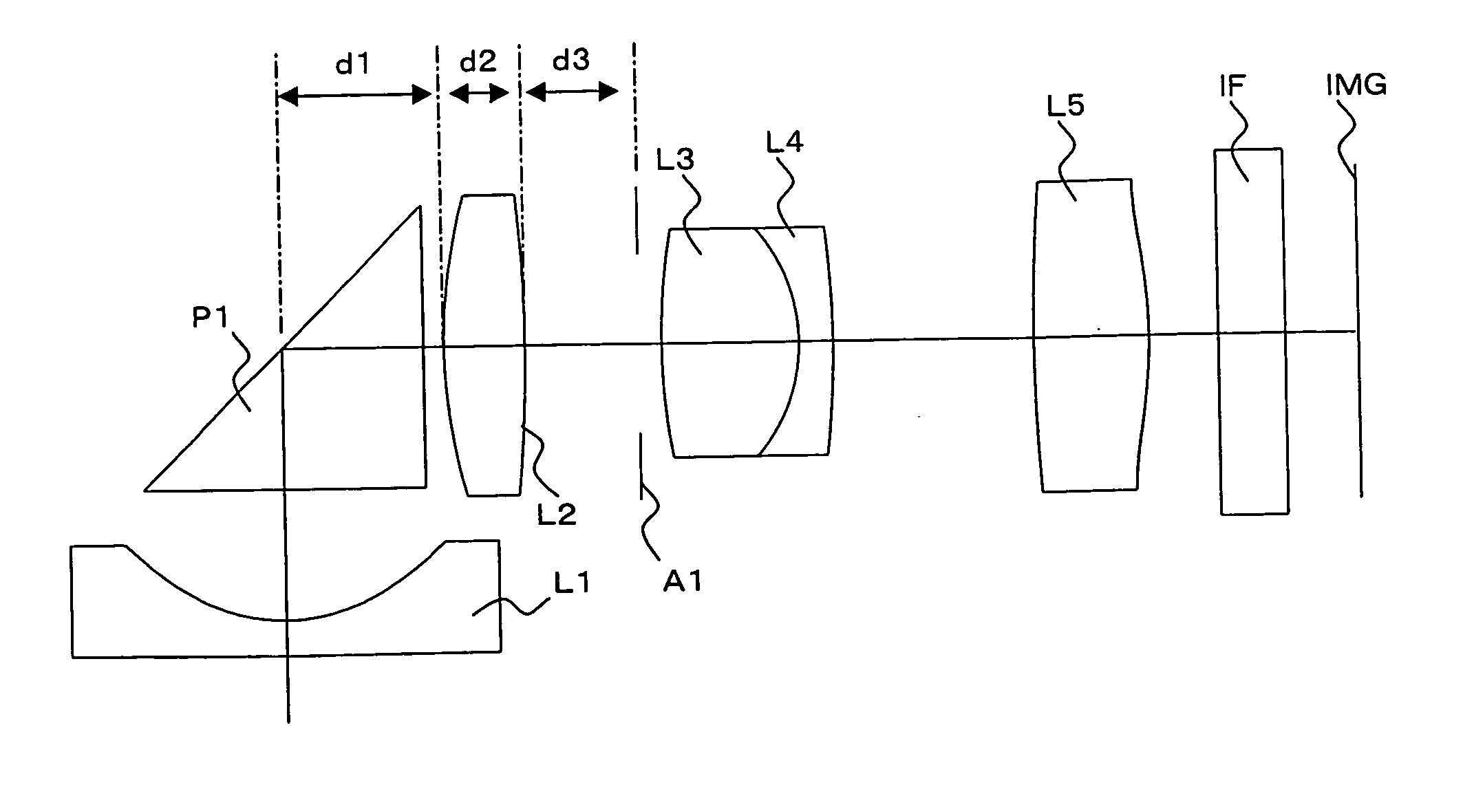
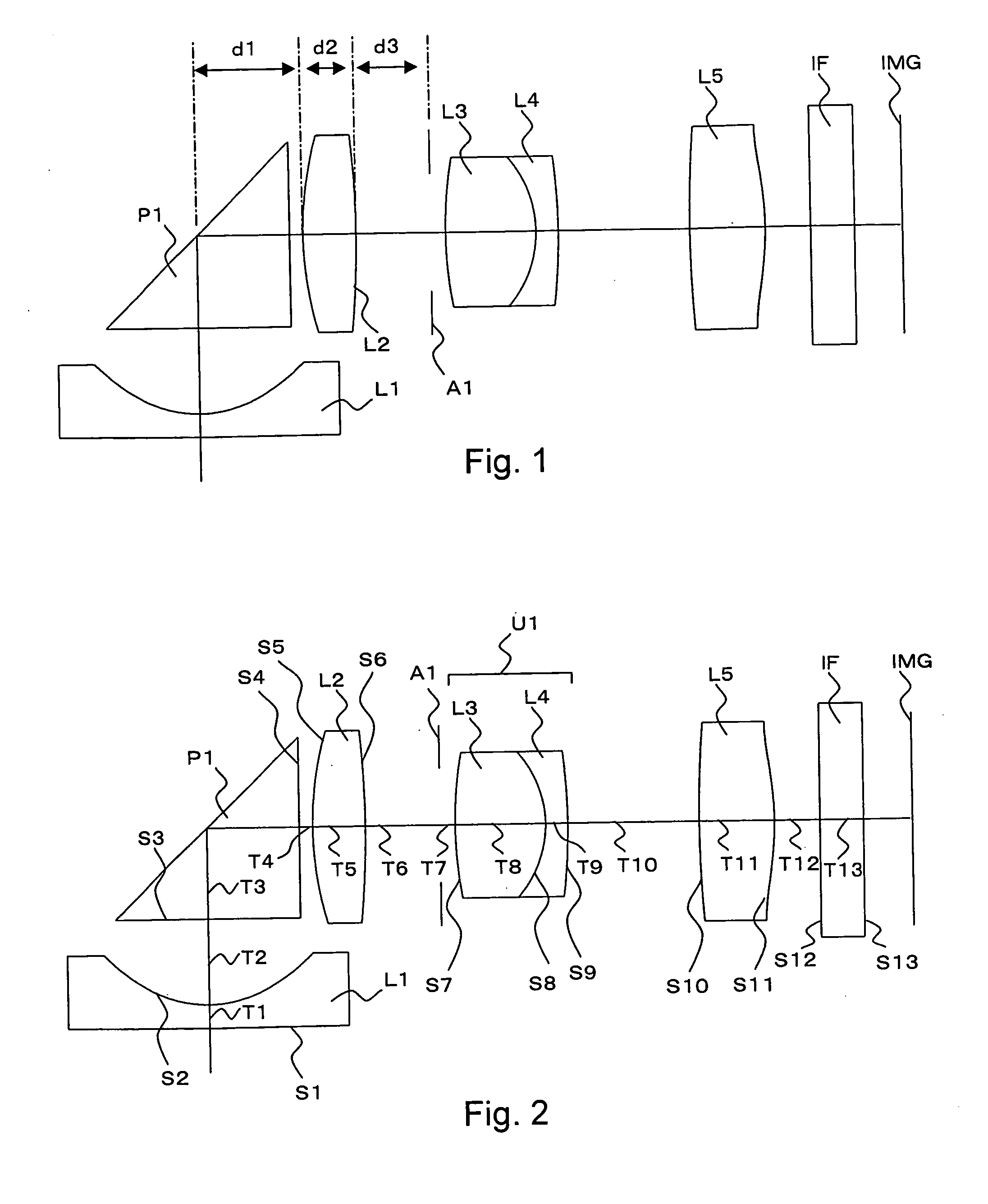
[0050] A first embodiment will now be described. FIG. 2 is a cross-sectional view of a wide angle lens system according to the first embodiment along an optical axis. The wide angle lens system depicted in FIG. 2 is the same as the above-described wide angle lens system shown in FIG. 1, and hence the explanation of the lens configuration will be omitted. Table 1 shows respective numeric values in the first embodiment. In Table 1, f is a combined focal length of an entire lens system constituting the wide angle lens system, Fno is an F number, and ω is a half field angle. Further, in FIG. 2 and Table 1, surface numbers Si (i=1, 2, 3 . . . ) denote an incidence surface and exist surface of light on an optical axis of each optical element constituting the wide angle lens system in order from an object side. Furthermore, in FIG. 2, intervals Ti (i=1, 2, 3 . . . ) designate on-axis intervals (mm) in order from the object side. Moreover, here, a reflecting surface position of a triangular...

third embodiment

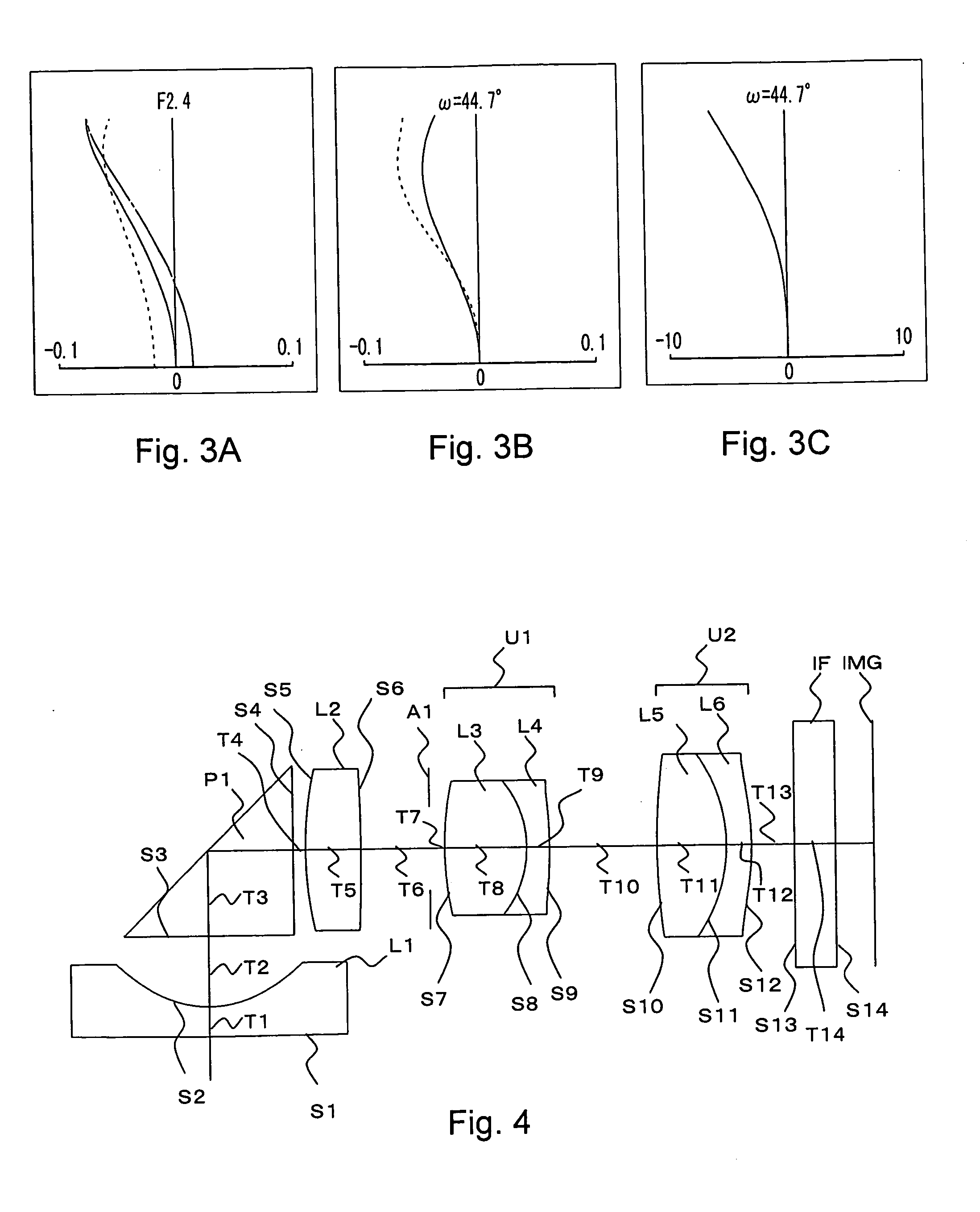
[0059] A third embodiment will now be described. FIG. 6 is a view showing a cross section of a wide angle lens system according to a third embodiment along an optical axis. A lens configuration of the wide angle lens system depicted in FIG. 6 is the same as that of the wide angle lens system shown in FIG. 2, and the explanation of the lens configuration is omitted.

[0060] Table 7 shows respective numeric values in the third embodiment. Moreover, Table 8 shows aspheric coefficients of surfaces formed into aspheric surfaces in the third embodiment. Additionally, Table 9 shows values of respective parameters of Conditions (1) to (4) in the third embodiment. It is to be noted that symbols in the respective tables are the same as those in Table 1 to Table 3. It is to be noted Table 7 shows that a last lens L5 is formed of a cycloolefin-polymer-based plastic material based on numeric values of nd and vd.

TABLE 7f = 3.88 Fno = 2.8 ω = 44.7°CURVATUREREFRAC-ABBESURFACERADIUSINTERVALTIVENUMB...


PUM


Abstract

There is provided a wide angle lens system configured to obtain excellent image forming performance even in a half field angle region of 40 degrees to 50 degrees. A wide angle lens system is constituted of a first lens having a negative refractive power, a light path bending member having no refractive power, a second lens having a positive refractive power, an aperture which adjusts a light amount, a first cemented lens formed by cementing a third lens having a positive refractive power and a fourth lens having a negative refractive power, a fifth lens having a positive refractive power, and an optically equivalent member which functions as a faceplate of an optical low-pass filter and a solid state imaging element.

Description

BACKGROUND OF THE INVENTION [0001] The present invention relates to a wide angle lens system and a camera provided with the wide angle lens system. [0002] In recent years, there has been increased demand for a reduction in size or thickness of a digital camera. Further, a demand for a reduction in size or thickness and cost saving is also high with respect to an imaging optical system mounted in a digital camera. In order to meet these demands, an imaging optical system in which optical elements such as a prism used to bend a light path halfway are arranged has come into practical use while the number of the optical elements is reduced. [0003] Further, in recent years, there has also been an increased demand for an imaging optical system having a wide field angle or an imaging optical system which is bright even if its F number is small in order to increase added value of a product while achieving excellent correction of aberration to cope with an increase in the number of pixels of...

Claims


Application Information

Patent Timeline
Patent Type & Authority Applications(United States)
IPC IPC(8): G02B13/04
CPCG02B13/04
Inventor KUSHIDA, TAROKAMBAYASHI, NOBUMASA
Owner MONUMENT PEAK VENTURES LLC
Why Eureka
Try Eureka