Multilayer capacitor

a multi-layer capacitor and capacitor technology, applied in the direction of capacitors, fixed capacitor details, fixed capacitors, etc., can solve the problems of insufficient reduction of esl, and difficulty in keeping voltage fluctuations accompanying such current fluctuations within the tolerances of power supplies, so as to prevent short circuits, reduce esl, and secure the distance between electrodes.

Active Publication Date: 2007-02-01
TDK CORPARATION
View PDF4 Cites 6 Cited by
  • Summary
  • Abstract
  • Description
  • Claims
  • Application Information

AI Technical Summary

Benefits of technology

[0021] Preferably, the first external electrodes and second external electrode are arranged on the first end face adjoining each other in a matrix. By arranging the external electrodes in a matrix in this way, high frequency currents are generated flowing in opposite directions in the first external electrodes and second external electrodes, the magnetic fields cancel each other out, and the ESL can be reduced.
[0022] Preferably, the first interlayer connection use columnar electrodes and the second interlayer connection use columnar electrodes are alternately arranged in the device body along the side faces of the device body. By arranging the interlayer connection use columnar electrodes along the side faces of the device body, there is no longer a need to form through holes at the centers of the internal electrode layers, so the electrode layers forming the capacitor can be increased in areas. Further, compared with the centers of the internal electrode layers, at the peripheries, even if the interlayer ...

Problems solved by technology

Keeping the voltage fluctuations accompanying such current fluctuations within the tolerances of the power supplies is becoming extremely difficult.
However, the increasingly higher operating frequencies of CPUs have led to faster speed and larger current fluctuations.
However, with a multilayer capacitor like in the first publication with pluralities of terminal electrodes provided on the four side faces and of a form for connection nea...

Method used


Image

  • Multilayer capacitor
  • Multilayer capacitor
  • Multilayer capacitor

Examples


Embodiment Construction

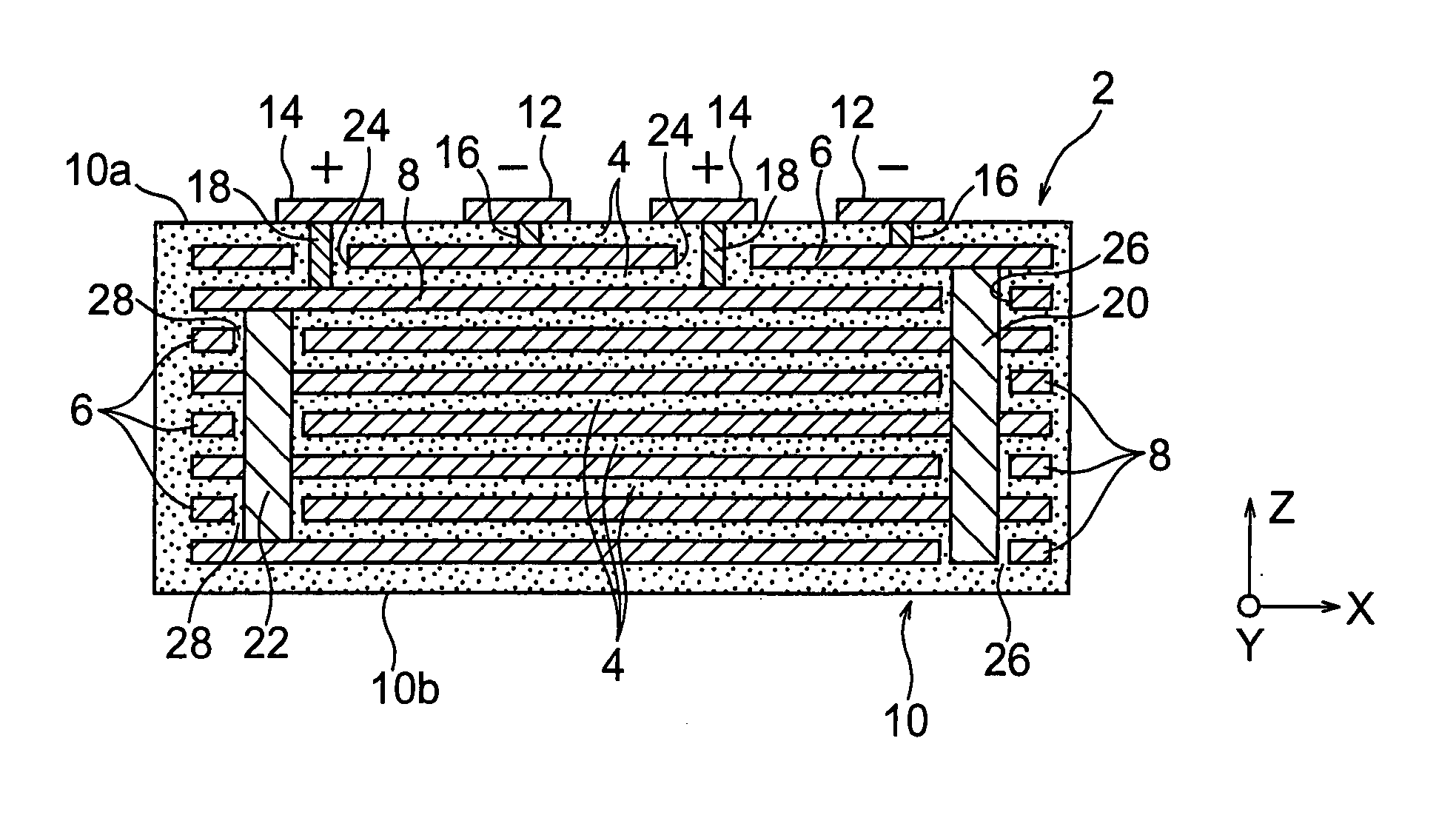
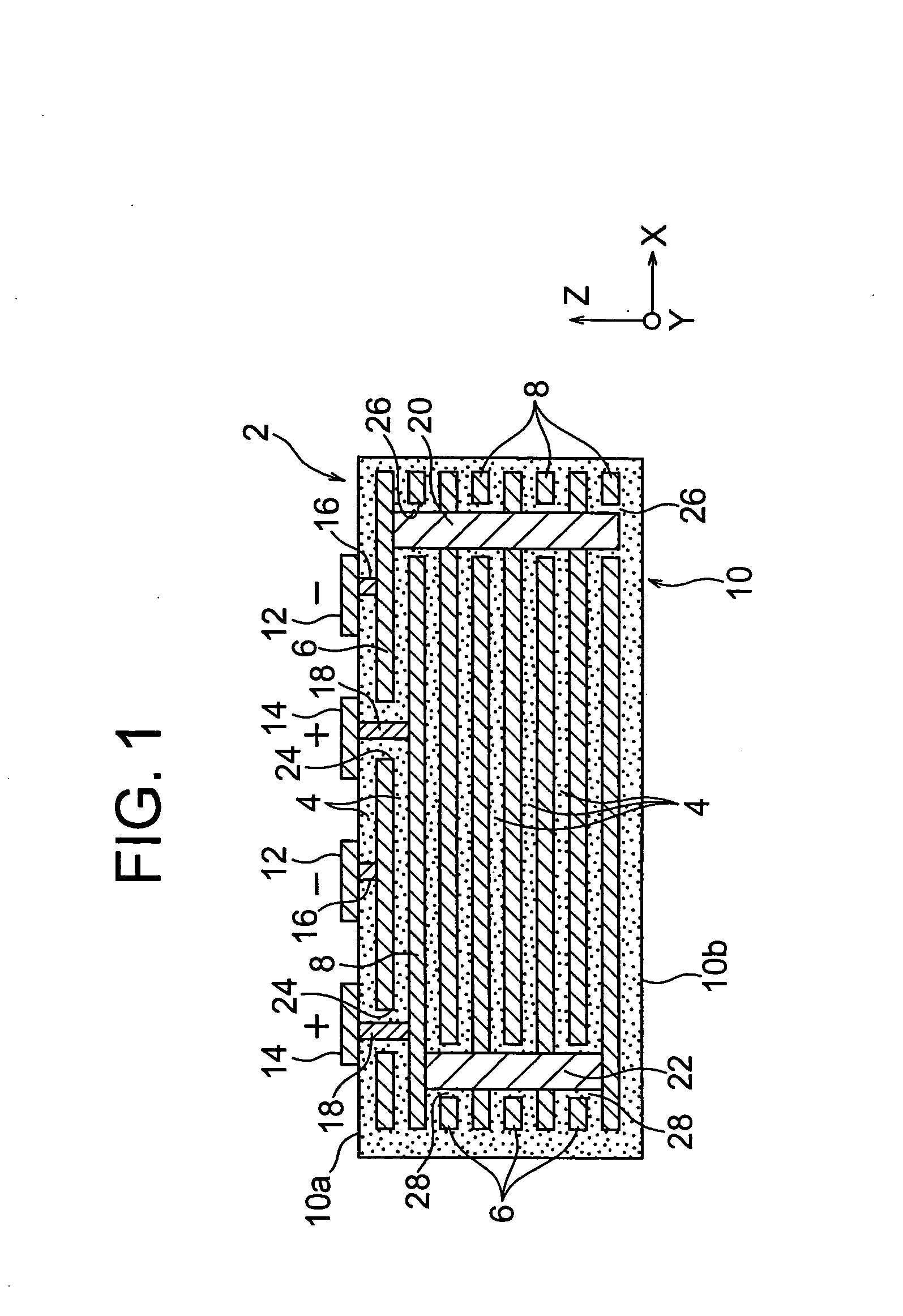
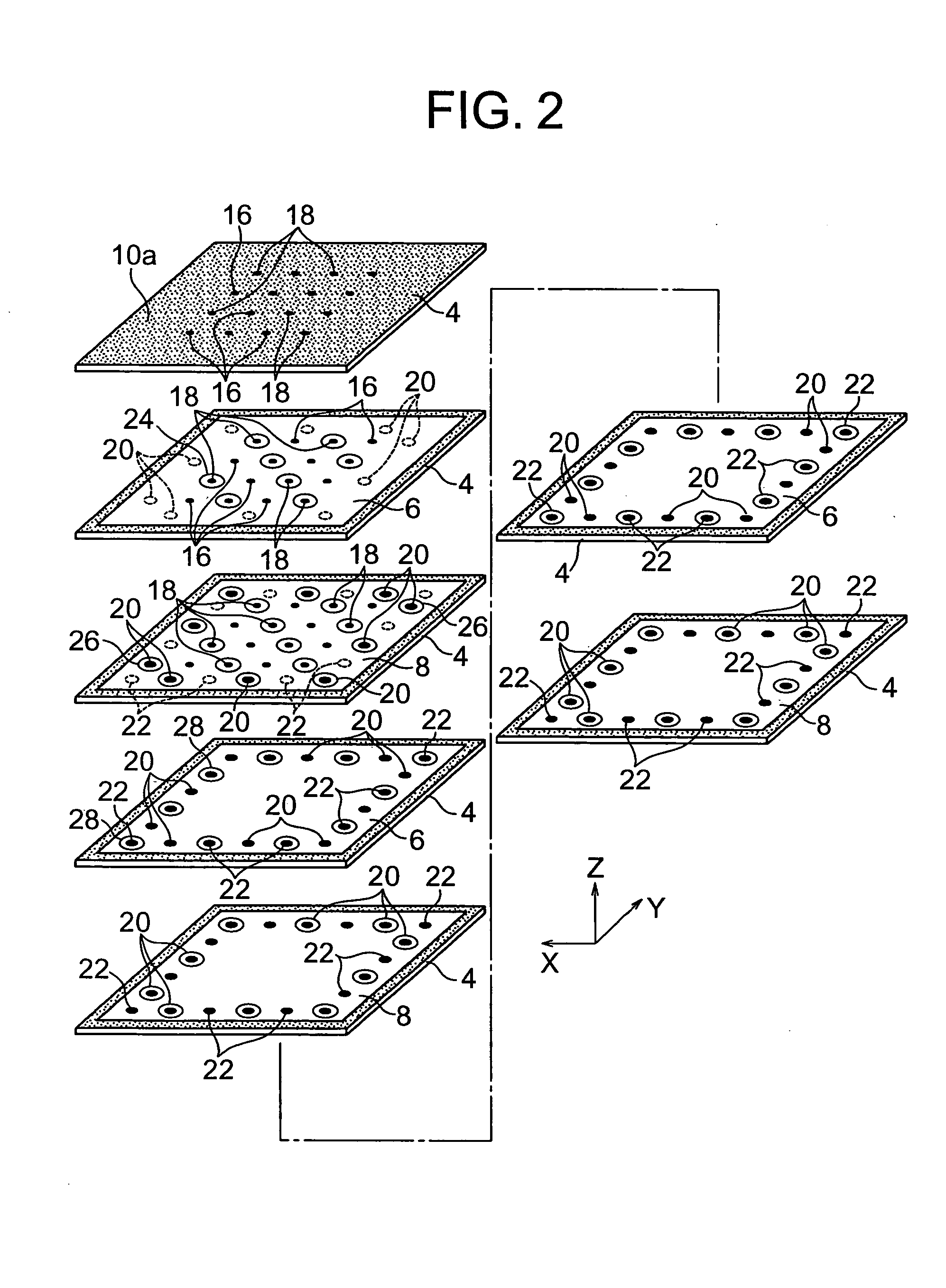
[0028] As shown in FIG. 1 to FIG. 3, a multilayer capacitor 2 according to an embodiment of the present invention has a device body 10. The device body 10 is provided with first external terminals 12 and second external terminals 14 arranged in a matrix at only a first end face 10a in the stacking direction (Z-axial direction) of the dielectric layers 4. The device body 10 is not provided with external terminals 12 and 14 at a second end face 10b and the four side faces 10c.

[0029] Inside the device body 10, first internal electrode layers 6 and second internal electrode layers 8 are alternately stacked via dielectric layers 4. The device body 10 is a rectangular parallelopiped in shape and is obtained by stacking and firing a plurality of ceramic green sheets for forming the dielectric layers 4 together with electrode paste layers for forming the internal electrode layers 6 and 8.

[0030] In the present embodiment, the vertical and horizontal dimensions L1 and L2 of the device body ...


PUM


Abstract

A multilayer capacitor comprised of dielectric layers stacked to form a device body in which a plurality of first internal electrode layers and a plurality of second internal electrode layers formed in planar shapes are alternately arranged while being separated through the dielectric layers, wherein the first external electrodes and second external electrodes are arranged at only a first end face of the device body, lead use columnar electrodes connect the internal electrode layers stacked close to the first end face of the device body and external electrodes, interlayer connection use columnar electrodes connect the internal electrode layers stacked at the inside of the device body, and the interlayer connection use columnar electrodes have cross-sectional areas larger than the cross-sectional areas of the lead use columnar electrodes.

Description

BACKGROUND OF THE INVENTION [0001] 1. Field of the Invention [0002] The present invention relates to a multilayer capacitor having through holes, more particularly relates to an easy-to-produce multilayer capacitor able to reduce the connection resistances between internal electrode layers in the stacking direction through the through holes while maintaining a low ESL without causing a reduction of the areas of the internal electrode layers. [0003] 2. Description of the Related Art [0004] In recent years, the central processing units (CPUs) used for data processing systems have been made higher in operating frequency and have remarkably increased in consumed current due to improvements in their processing speed and their higher integration. Further, along with this, operating voltages have been reduced as a general tendency along with the reduction of the consumed power. Therefore, in the power supplies for supplying power to the CPUs, faster and larger current fluctuations are occu...

Claims


Application Information

Patent Timeline
IPC IPC(8): H01G4/236
CPCH01G4/30H01G4/232
Inventor TOGASHI, MASAAKIAHIKO, TAISUKE
Owner TDK CORPARATION
Why Eureka
Try Eureka