
Blade-thru condenser and heat dissipation system thereof

Inactive Publication Date: 2007-02-01
ARTICCHOKE ENTERPRISES
View PDF11 Cites 18 Cited by
  • Summary
  • Abstract
  • Description
  • Claims
  • Application Information

AI Technical Summary

Benefits of technology

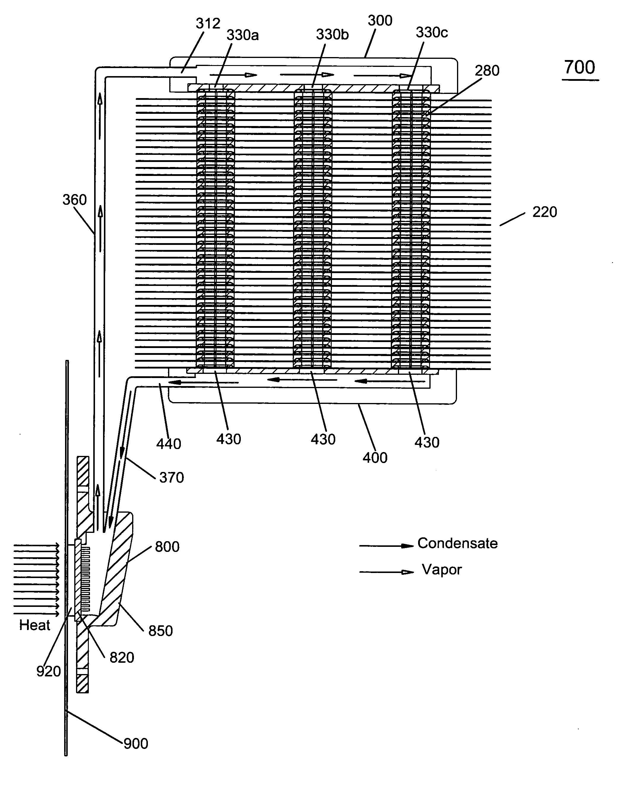
[0012] In yet a further embodiment, the condenser core of the blade-thru condenser comprises a plurality of substantially planar blades joined one on top of another along a longitudinal axis of the condenser core by multiple spacer rings disposed between two adjacent blades. Each blade comprises multiple condensation chambers formed within interiors of the spacer rings. The blades are so aligned that the multiple condensation chambers of each of the blades are disposed above the multiple condensation chambers of the blade immediate underneath, thereby forming multiple phase exchange columns. Each condensation chamber has one or m

Problems solved by technology

With the never-ending increase of computing power, effectively cooling a CPU has become a technical challenge.
Therefore, the conventional heat dissipation devices have very limited capacities and are inadequate for cooling the high power CPU, which operates with a power of about 235 watts.
However, liquid cooling devices are expensive, noisy and difficult to maintain.

Method used


Image

  • Blade-thru condenser and heat dissipation system thereof
  • Blade-thru condenser and heat dissipation system thereof
  • Blade-thru condenser and heat dissipation system thereof

Examples


Embodiment Construction

[0043] In one aspect, the present invention provides a blade-thru condenser for facilitating a high efficiency liquid-gas phase exchange and heat dissipation.

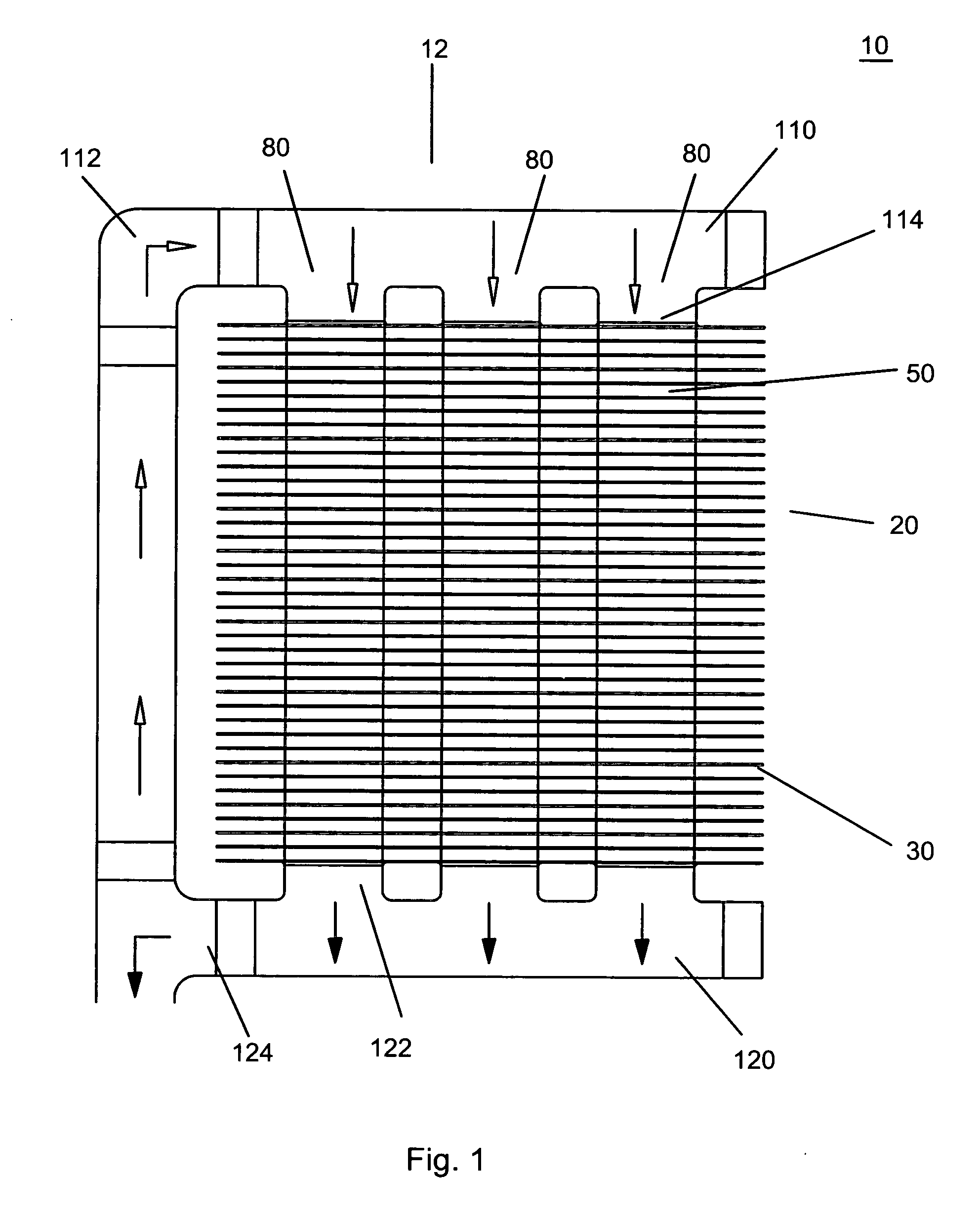
[0044] In one embodiment, condenser 10 comprises a condenser core 20, an input manifold 110, and an output manifold 120, as shown in FIG. 1.

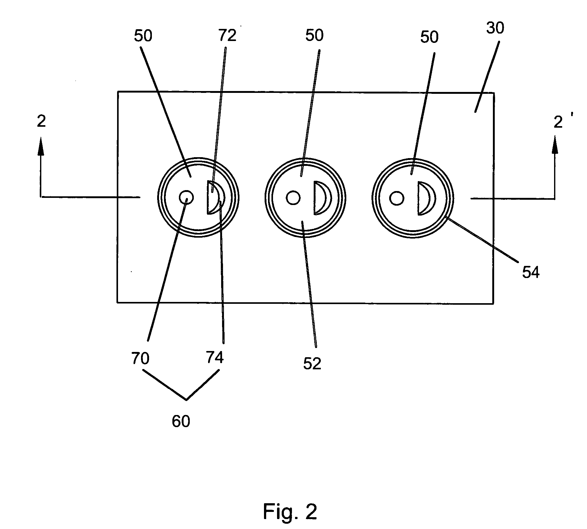
[0045] Referring to FIGS. 1, 2, 3, 3A and 3B, condenser core 20 comprises a plurality of substantially planar blades 30 joined one on top of another along a longitudinal axis 12 of condenser 10 by joint interfaces 40 formed between two adjacent blades. Each layer of blades 30 has multiple condensation chambers 50. In the embodiment shown, condensation chambers 50 are drawn chambers, which are formed monolithically in each blade. On floor 52 of each condensation chamber 50 there can be one or more apertures, or openings, 60, which permit vapor and condensate to pass therethrough and cause vibration of floor 52 of condensation chamber 50. As shown, a plurality of layers of blades 30 are so ...


PUM


Abstract

A condenser includes a condenser core, input and output manifolds connected therewith. The condenser core has a blade-thru structure, which is formed by a plurality of layers of thin metal blades stacked on top of another by joint interfaces or joined by spacer rings between two adjacent blades. Each layer of the blades includes condensation chamber(s), wherein the floor of the chamber is monolithic with the rest of the blade. The blades are so aligned that the condensation chamber(s) of each blade are on top of the condensation chamber(s) of the blade immediate underneath, thereby forming phase exchange column(s). Each condensation chamber has one or more apertures on the floor thereof, permitting vapor and condensate to pass therethrough and causing vibration of the chamber floor. Further disclosed is a heat dissipation system utilizing the blade-thru condenser, as well as a computer system utilizing the heat dissipation system.

Description

CROSS REFERENCE TO RELATED APPLICATION [0001] This application claims the benefit under 35 USC 119(e) of the provisional patent application Ser. No. 60 / 703,945, filed Jul. 30, 2005, and Ser. No. 60 / 797,848, filed May 6, 2006, which are herein incorporated by reference in their entirety.FIELD OF THE INVENTION [0002] The present invention relates to a condenser and a heat dissipation system utilizing the condenser. More specifically, the condenser has a blade-thru structure and further utilizes vibration to enhance the efficiency of heat exchange. BACKGROUND OF THE INVENTION [0003] With the never-ending increase of computing power, effectively cooling a CPU has become a technical challenge. The present temperature limit for a CPU is approximately 60° C. As the power of a CPU increases, more heat is generated; therefore, the CPU requires a higher efficiency and capacity of the heat dissipation device in order to provide effective thermal management to the computer system. Heat dissipat...

Claims


Application Information

Patent Timeline
IPC IPC(8): H05K7/20
CPCF28D15/0266H01L23/427H01L2924/0002H01L2924/00
Inventor SILVERSTEIN, PAUL
Owner ARTICCHOKE ENTERPRISES
Learn More