Retaining tool with rotational locating device

Inactive Publication Date: 2007-02-01
ASIA VITAL COMPONENTS SHENZHEN CO LTD
View PDF6 Cites 16 Cited by
  • Summary
  • Abstract
  • Description
  • Claims
  • Application Information

AI Technical Summary

Benefits of technology

[0012] In order to solve the preceding problems, an object of the present invention is to provide a retaining tool with rotational locating device with which tight contact between the heat sink and the CPU is capable of reaching to decrease the thermal resistance and enhancing the binding force to the heat sink and the CPU significantly.
[0013] Another object of the present invention is to provide a retaining tool with rotational locating device in which a locator rotates and is located by means of a guiding groove with a preset specific path to increase the binding force to the CPU and the heat sink greatly.
[0014] A further object of the present invention is to provide a retaining tool with rotational locating device with which the binding force to the CPU and the heat sink intersects the locking force of the locator so as to avoid loc

Problems solved by technology

Due to electronic product such as computer being popularly used and being widely applied to any fields, the electronic technology industry develops rapidly toward high speed operation and high data storage capacity and it results in high heat during the electronic parts runni

Method used


Image

  • Retaining tool with rotational locating device
  • Retaining tool with rotational locating device
  • Retaining tool with rotational locating device

Examples


Example

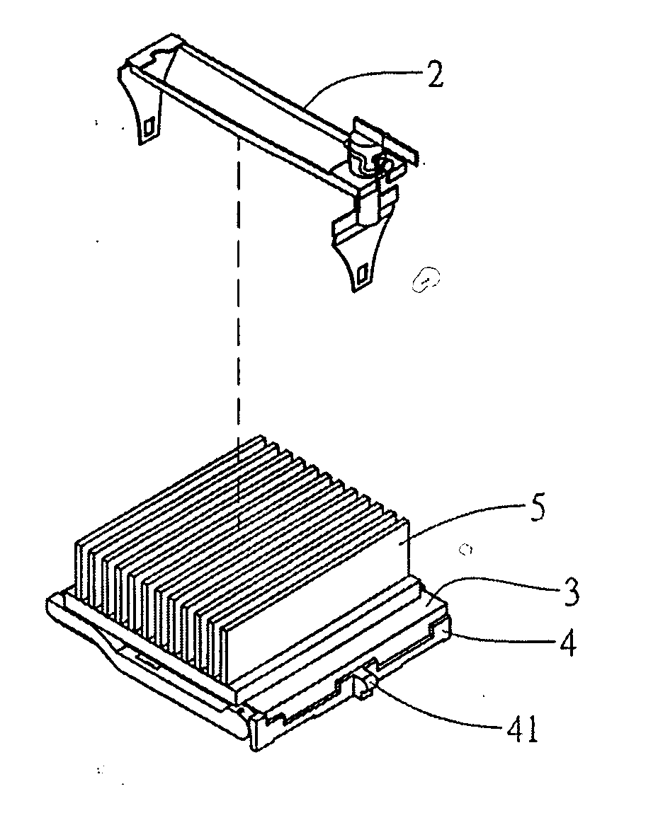
[0035] Referring to FIGS. 3, 4, 5 and 6, the first embodiment of a retaining tool with rotational locating device according to the present invention provides a retaining tool 2, which includes a main frame 21 and a locator 22.

[0036] The main frame 21 is inserted with the locator 22. The main frame 21 has a lock part 210 at an end thereof for fixedly attaching with a jut 41 protruding outward from a lateral side of a joining seat 4, which bears a CPU (central processing unit 3). The main frame 21 extends from a lateral side of a heat sink 5 to another side of the heat sink 5 so as to allow the heat sink 5 touching the CPU 3 tightly for guiding heat of the CPU 3 out via the heat sink 5. The locator 22 is inserted into another end of the main frame 21.

[0037] The locator 22 has a lock part 220 to engage with another jut 41 at another lateral side of the joining seat 4 opposite to the lock part 210 and the lock part 220 is driven with the locator 22 to force the heat sink 5 keeping con...

Example

[0040] Referring to FIGS. 7 and 8, the second embodiment of a retaining tool with rotational locating device according to the present invention is illustrated. The difference of the present embodiment from the first embodiment is in that the retaining tool 2 provides an elastic member 24 between the main frame 21 and the locking unit 222 and the elastic member 24 has a shape of bow, character “C” or an inverted character “C” or any other suitable shape with a hole at the top thereof for being passed through by the locking unit 222. The elastic member 24 biases the locking unit 222 and the main frame respectively for increasing stability of the locking unit 222 and avoiding the locking unit shaking resulting from vibration. Further, the elastic member 24 is helpful for the locking unit 222 engaging with the jut 41 of the joining seat 4.

Example

[0041] Referring to FIGS. 9 and 10, the third embodiment of a retaining tool with rotational locating device according to the present invention is illustrated. The difference of the present embodiment from the second embodiment is in that the elastic member 24 extends a clip part 240 to catch the locking unit 222 for increasing binding force of the elastic member 24 with the locking unit 222.


PUM


Abstract

A retaining tool with rotational locating device includes a main frame and a locator. The main frame provides a first lock part at an end thereof. The locator rotationally inserts through the main frame next to the other end thereof. The locator further includes an adjustable unit and a locking unit attached to the adjustable unit. The locking unit has a second lock part at the lower section thereof corresponding to the first lock part. The lock parts engage with an object and the locking unit with the second lock part is capable of moving vertically in case of the adjustable unit being turned horizontally. The object is forced to keep contact other objects tightly or to release from contacting other objects.

Description

BACKGROUND OF THE INVENTION [0001] 1. Field of the Invention [0002] The present invention is related to a retaining tool with rotational locating device and particularly to a rotational locating device capable of fixing a heat sink to a central processing unit (CPU). [0003] 2. Brief Description of the Related Art [0004] Due to electronic product such as computer being popularly used and being widely applied to any fields, the electronic technology industry develops rapidly toward high speed operation and high data storage capacity and it results in high heat during the electronic parts running under high speed. [0005] Taking the host unit of a computer as an example, most heat therein is generated from the CPU and the heat staying in the CPU exceeding the allowable value leads to shut down of the computer. Further, in order to solve problem relating to electromagnetic wave radiation, the host unit is enclosed with a casing. Under this circumference, how to release the heat from the ...

Claims


Application Information

Patent Timeline
IPC IPC(8): H05K7/20
CPCH01L23/4093H01L2924/0002Y10T24/44034H01L2924/00
Inventor LIN, SHENG-HUANG
Owner ASIA VITAL COMPONENTS SHENZHEN CO LTD
Why Eureka
Try Eureka