
Phase mapping for QPSK/QBL-MSK waveform

a phase mapping and waveform technology, applied in the field of communication, can solve the problems of reducing the spectral efficiency of the regrowth process, reducing the processing gain degradation and the complexity of the table lookup, and reducing the complexity of the processing gain degradation and the table lookup

Active Publication Date: 2007-02-01
HARRIS GLOBAL COMMUNICATIONS INC
View PDF16 Cites 10 Cited by
  • Summary
  • Abstract
  • Description
  • Claims
  • Application Information

AI Technical Summary

Benefits of technology

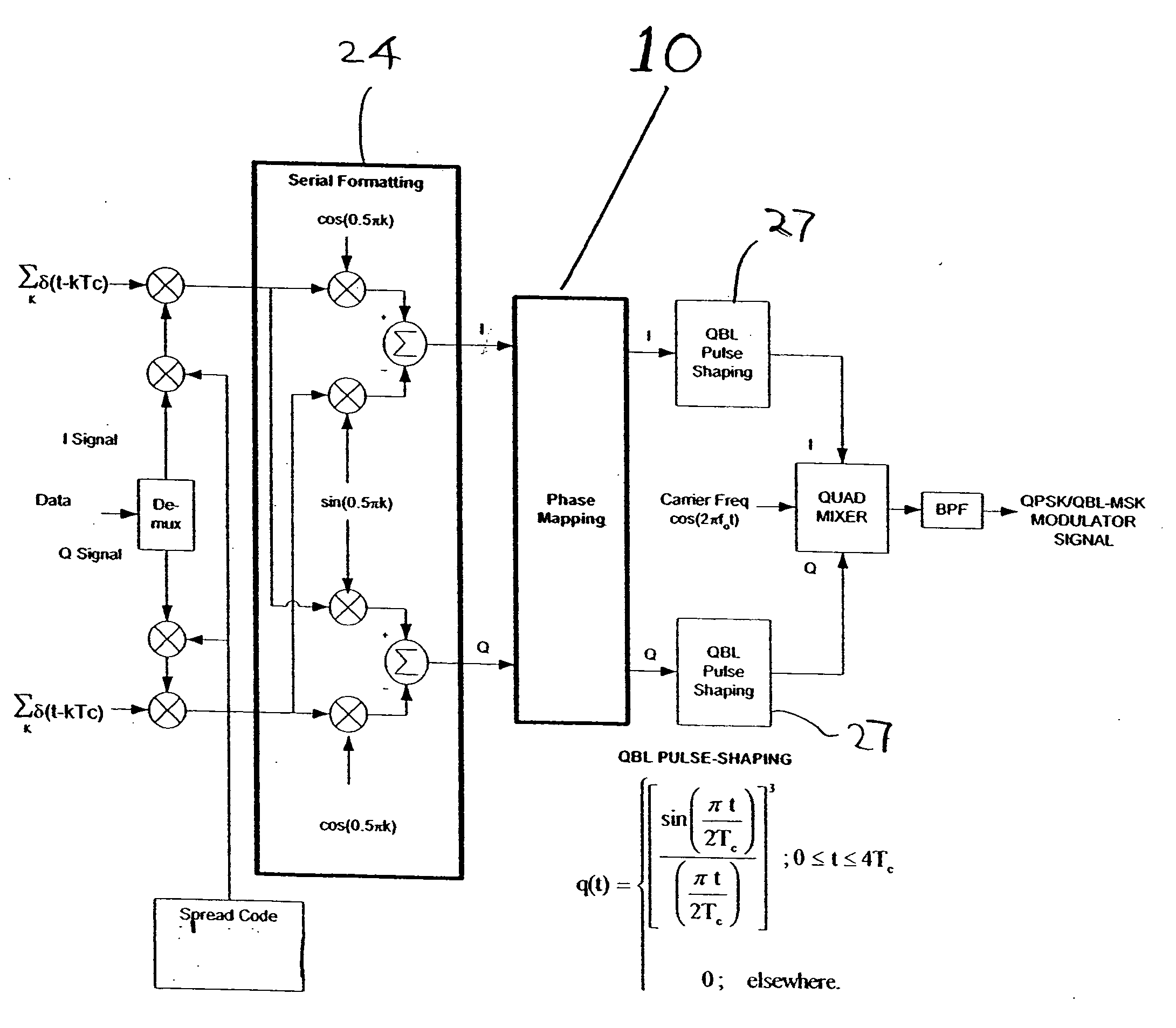
[0013] To reduce the processing gain degradation and table look-up complexity a new phase mapping is performed at the symbol boundary, which reduces processing gain degradation and look-up table complexity.

Problems solved by technology

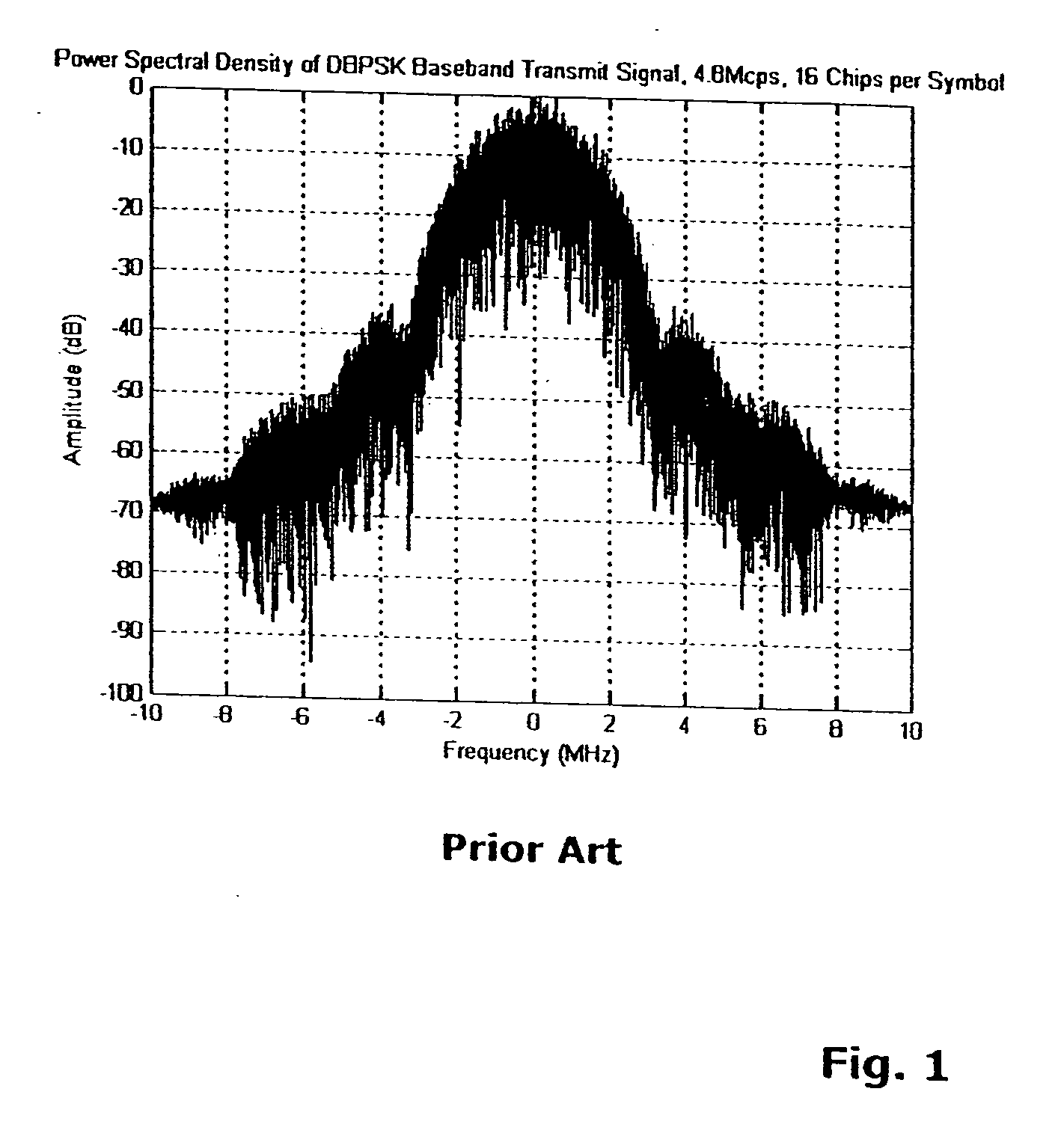
Since QBL-MSK is not a constant envelope modulation waveform, nonlinear Class C power amplifications results in regrowth in the spectrum sidelobe levels.
Spectral efficiency is lost by this regrowth process.
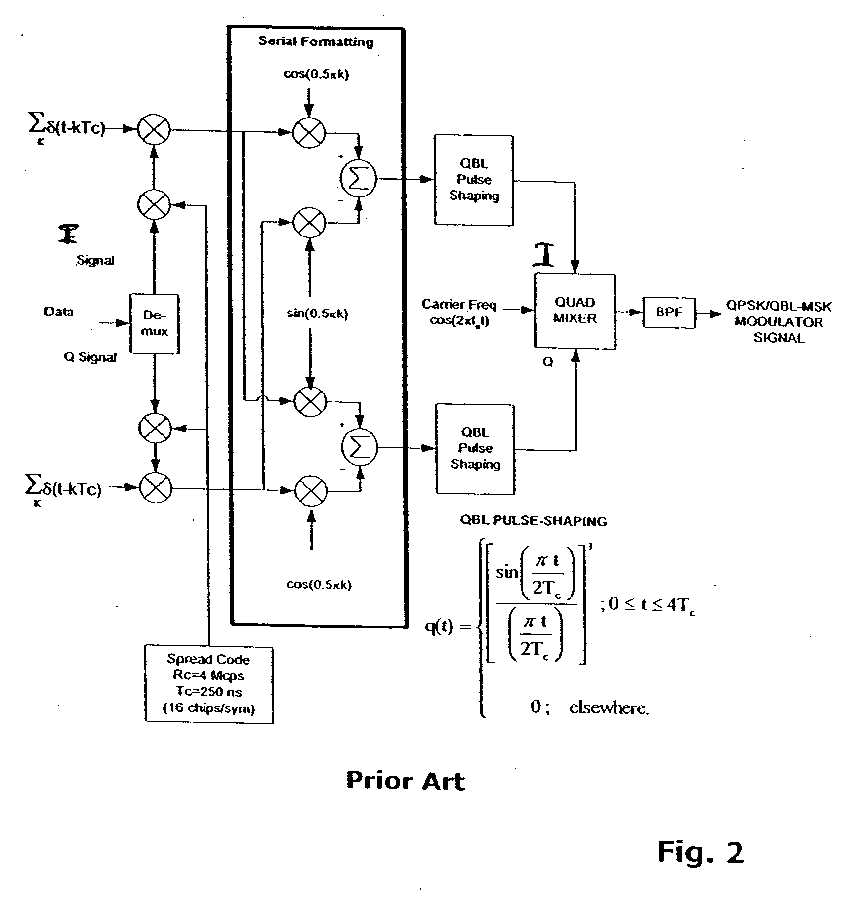
Because QPSK data modulation modifies the spread spectrum QBL-MSK waveform, Amoroso's nonlinear results are not valid for this waveform.
For this condition the RF envelope goes to zero, which is undesirable for a near constant envelope modulation waveform, like QBL-MSK.
These large RF envelope deviations result in increased sidelobe level regrowth for nonlinear Class C power amplification.
Severe RF envelope distortion, however, as shown in FIGS. 4A, 4B and 4C, results when both the I and Q signals go to zero at the same point in time, causing the RF envelope to go to zero.

Method used


Image

  • Phase mapping for QPSK/QBL-MSK waveform
  • Phase mapping for QPSK/QBL-MSK waveform
  • Phase mapping for QPSK/QBL-MSK waveform

Examples


Embodiment Construction

[0044] The phase mapping of the present invention requires four signal states in the QBL-MSK modulator. FIG. 8 shows two unique conditions for the I signal, over time interval 0 to 2TC, where TC is the chip period. FIG. 8 also shows the chip pulses that make up the two unique signal conditions. From these two conditions the four possible I signals can be generated by either inverting or not-inverting one of the two signal conditions. Since the Q signal is a time shift version of the I signal, by a chip period, with the Q data and Q chips multiplying the chip pulses, the same approach can be used to generate four possible Q signals within each chip period. This approach allows use of a look-up table (LUT) to implement the mapping performed by the present invention. For BPSK data modulation, the signal structure does not change with the data modulation. For QPSK data modulation with phase mapping, the signal structure, at the symbol boundaries, is affected by the data modulation when ...


PUM


Abstract

A method is described of pulse shaping a modulated sequence spread signal having serially formatted in-phase (I) and quadrature (Q) waveforms, each waveform includes a predetermined number of chips per symbol. The method includes (a) examining adjacent chips of the I and Q waveforms at a symbol boundary; (b) determining that one of the I or Q waveforms, at the symbol boundary, includes two adjacent first and second chips separated by a single chip period, where the first chip belongs to a previous symbol and the second chip belongs to a present symbol; (c) determining whether the first and second chips are of the same value; (d) if step (c) determines that the chips are of the same value, then extending a peak value between the first and second chips, and zeroing the other waveform of the I or Q waveform during the extended duration of the peak value; and (e) if step (c) determines that the chips are of opposite values, then zeroing one of the first chip or second chip, and inserting a chip into the other waveform of the I or Q waveform during the duration of the zeroed one pulse. Step (e) includes inserting the chip into the other waveform, wherein the inserted chip has a value that is the same as an immediately previous chip value; and extending a peak value between the immediately previous chip and the inserted chip to provide a flat-top there-between.

Description

CROSS REFERENCE TO RELATED APPLICATIONS [0001] This application claims priority of U.S. Provisional Patent Application Ser. No. 60 / 703,179, filed Jul. 28, 2005.STATEMENT REGARDING FEDERALLY SPONSORED RESEARCH [0002] This invention was made with Government Support Under Agreement No. DAAB07-03-9-K601 awarded by the United States Army. The Government has certain rights in the invention.FIELD OF THE INVENTION [0003] The present invention relates, in general, to the field of communication. More specifically, it relates to spread-spectrum communication. Still more specifically, it relates to phase mapping of modulated sequence spread signals. BACKGROUND OF THE INVENTION [0004] Disclosure of the present invention is facilitated by U.S. Pat. No. 5,818,867 issued on Oct. 6, 1998 to Donald J. Rasmussen, which is hereby incorporated by reference. [0005] Quasi-bandlimited minimum shift keying (QBL-MSK) pulse-shaping proposed by Frank Amoroso provides a significant improvement in modulator spec...

Claims


Application Information

Patent Timeline
IPC IPC(8): H04J11/00
CPCH04L25/03834H04L27/2017H04L27/2014H04L27/2003
Inventor RASMUSSEN, DONALD JOHNMULHOLLAND, DELBERT TODD
Owner HARRIS GLOBAL COMMUNICATIONS INC
Learn More