PON system and logical link allocation method

a technology of logical link allocation and pon system, which is applied in the field of pon system and logical link allocation method, can solve the problems of impeded ftth spread, non-patent document does not particularly disclose the method for allocating logical link identifier, and high introduction cost, so as to increase the utilization efficiency of the network

Inactive Publication Date: 2007-02-01
NEC CORP
View PDF4 Cites 47 Cited by
  • Summary
  • Abstract
  • Description
  • Claims
  • Application Information

AI Technical Summary

Benefits of technology

[0021] In the invention, the logical link is dynamically allocated in accordance with the contents of the packet passing through the PON system. Accordingly, no logical link not actually used is set wastefully. That is, the use of logical link can be concentrated on the traffic actually required, so that the utilization efficiency of the network can be increased.
[0022] Also, the dynamic control for logical link allocation is automatically performed by judging whether

Problems solved by technology

The optical fiber allows high-speed communications but has higher introduction costs than that of copper wire, which impeded the spread of the FTTH.
However, the non-patent document does not particularly disclose the method for allocating the logical link identifier.
Accordingly, in the case where the logical link identifier is individually allocated for each service, such as multicast distribution, video on-demand or voice, there is a risk that the first to third problems as described below may occur.
Since the logical link identifier is statically allocated, an up band secured by the logical link is wasted whe

Method used


Image

  • PON system and logical link allocation method
  • PON system and logical link allocation method
  • PON system and logical link allocation method

Examples


first embodiment

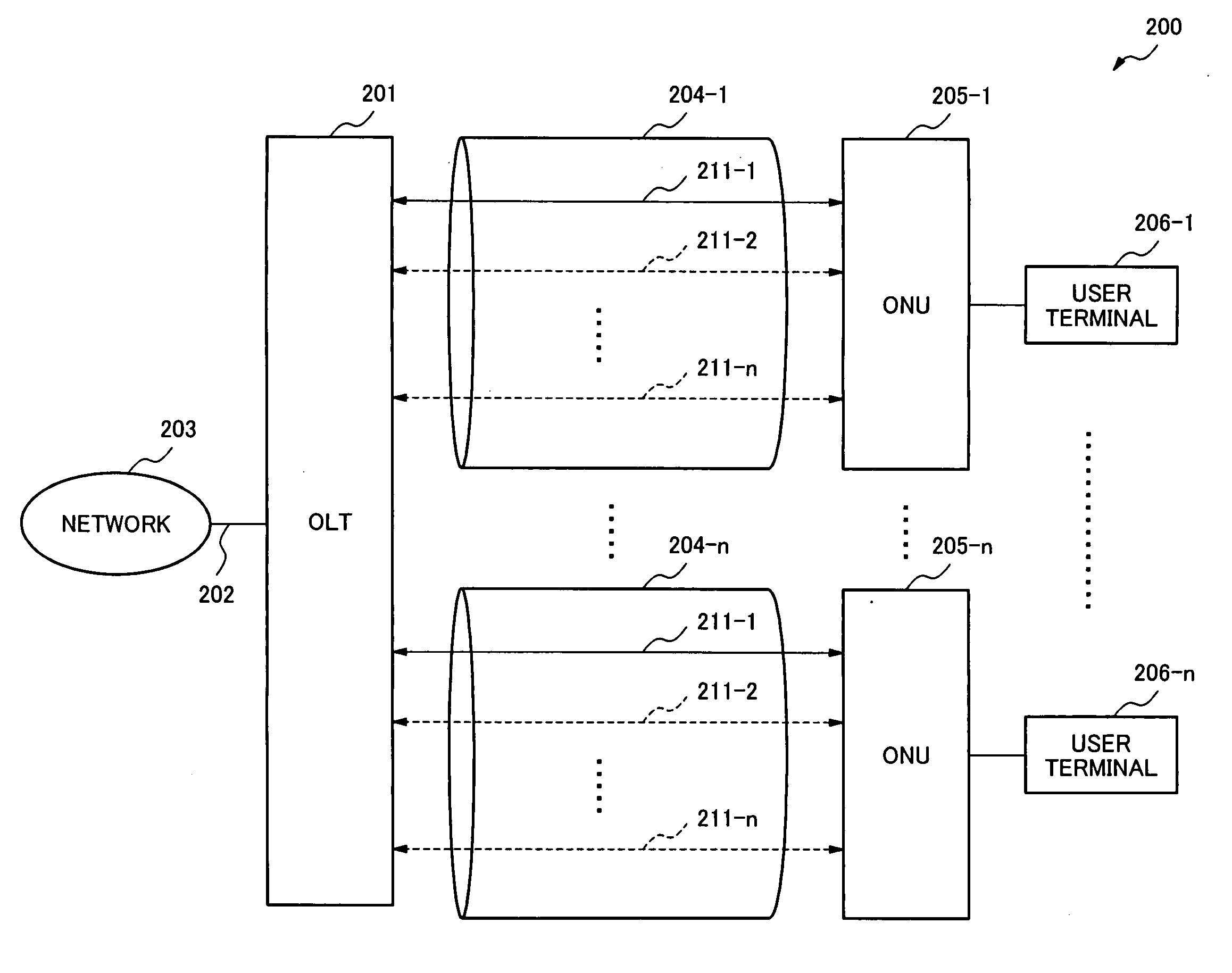
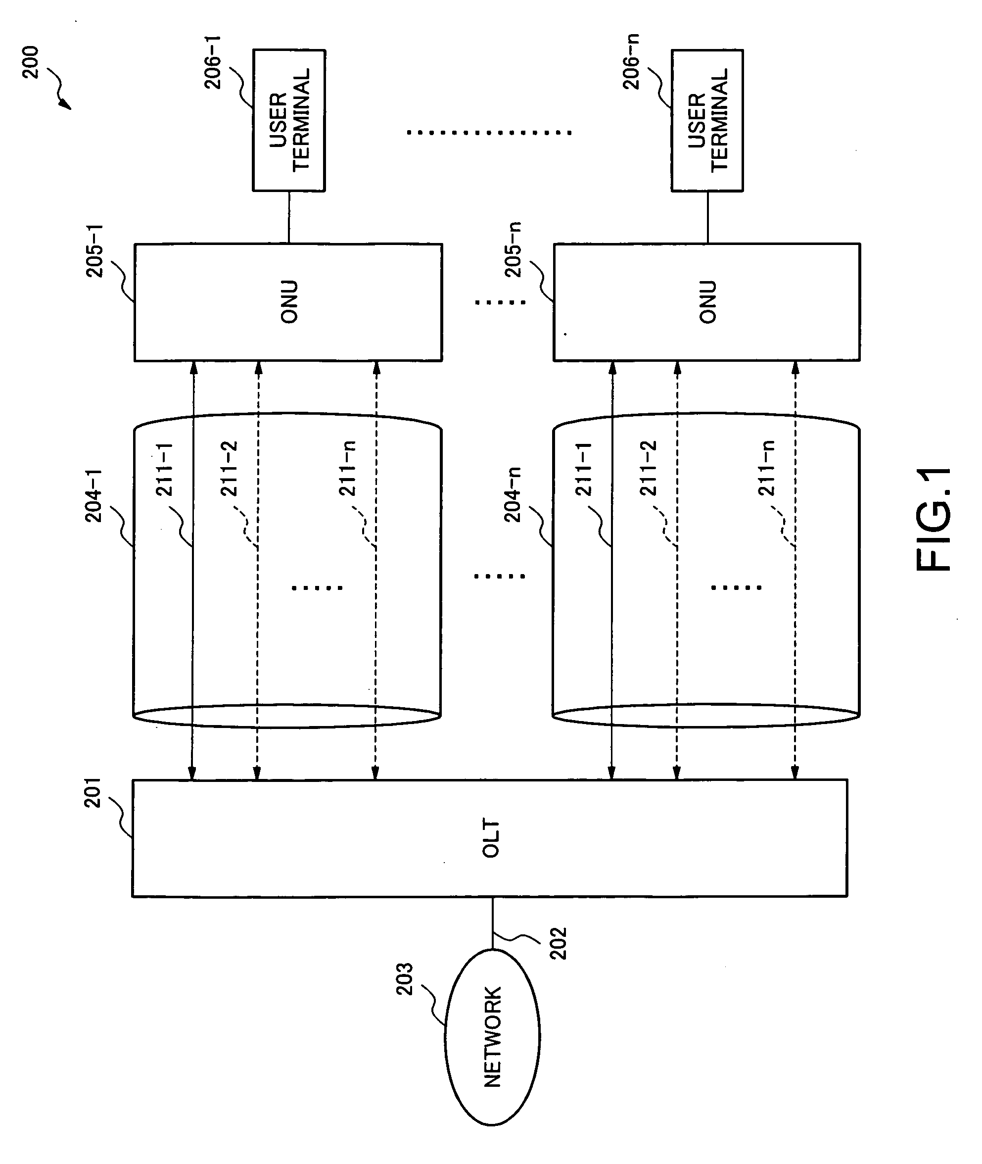
[0042]FIG. 1 is a control block diagram of a PON system 200 according to the present invention. The PON system 200 comprises an OLT (Optical Line Terminal) 201 for connecting to a network 203 to be accessed by user terminals 206-1 to 206-n, and a plurality of ONUs (Optical Network Unit) 205-1 to 205-n each connecting to the respective user terminals 206-1 to 206-n. The OLT 201 and the ONUs 205-1 to 205-n are physically connected with each other by physical connection means 204-1 to 204-n such as optical fibers split into a plurality of paths by an optical signal splitter, not shown. The network 203 and the OLT 201 are connected via an interface 202 conforming to the Ethernet (registered trademark). The standard of physical connection means 204-1 to 204-n may be the 1000BASE-PX, for example.

[0043] A plurality of logical links 211-1 to 211-n are set for each of the physical connection means 204-1 to 204-n. The logical links 211-1 to 211-n can be classified into two kinds. A first logi...

second embodiment

[0074]FIG. 10 is a control block diagram of a PON system 500 according to the invention. The same parts are designated by the same numerals throughout FIGS. 1 and 10, and the explanation is omitted properly.

[0075] The PON system 500 comprises an OLT 501 for connecting to the network 203 to be accessed by the user terminals 206-1 to 206-n, and a plurality of ONUs 505-1 to 505-n each connecting to the respective user terminals 206-1 to 206-n. The OLT 501 and the ONUs 505-1 to 505-n are connected with each other by physical connection means 504-1 to 504-n such as optical fibers split into a plurality of paths by an optical signal splitter, not shown. The network 203 and the OLT 501 are connected via the interface 202 conforming to the Ethernet (registered trademark).

[0076] In the PON system 500, a monitor logical link 511 as indicated by the solid line is not individually allocated for the ONUs 505-1 to 505-n, as in the PON system 200, but is shared among the ONUs 505-1 to 505-n. The ...


PUM


Abstract

A PON (Passive Optical Network) system, which is installed in an access network for connecting a user terminal to a network and can improve the utilization efficiency of the network, is provided. The PON system comprises an OLT (Optical Line Terminal) and at least one ONU (Optical Network Unit), and the OLT connects with the network and the ONU accommodates a user terminal and connected to the OLT via an optical fiber. A logical link generation or deletion condition table and a logical link identifier management table are provided for allocating logical links to be used between the OLT and the ONU. The logical link generation or deletion condition table defines generation or deletion conditions of logical link depending on the traffic (or service) class indicated by contents of a packet passing through the PON system. The logical link identifier management table contains logical link information to be allocated, and a content of this table is added or deleted by the control with referring to the logical link generation or deletion condition table. Whenever the packet is received, the PON system peeps in the contents of the packet, and allocates an appropriate logical link in accordance with the contents.

Description

BACKGROUND OF THE INVENTION [0001] 1. Field of the Invention [0002] The present invention relates to a PON (Passive Optical Network) system and a logical link allocation method. [0003] 2. Description of the Related Art [0004] An access network such as an FTTH (Fiber To The Home) that provides Internet connections employing optical fibers is known. The optical fiber allows high-speed communications but has higher introduction costs than that of copper wire, which impeded the spread of the FTTH. [0005] Thus, a PON system in which one optical fiber is shared among plural users to suppress the introduction costs of FTTH is well known. The configuration of a typical PON system is disclosed in Japanese Patent Application Laid-Open No. 2004-312633. FIG. 18 is a control block diagram of the typical PON system 100 as disclosed in this document. The PON system 100 comprises an OLT (Optical Line Terminal) 102 for connecting to a network 101, and a plurality of ONUs (Optical Network Unit) 108 e...

Claims


Application Information

Patent Timeline
IPC IPC(8): H04J14/00H04B10/27H04B10/272H04L12/44
CPCH04J14/02H04B10/27H04B10/25H04L12/44H04L65/40
Inventor OOGUSHI, SADAICHIROUTANAKA, MASASHI
Owner NEC CORP
Why Eureka
Try Eureka