Transport system

a technology of transportation system and public transportation, applied in the field of transportation system, can solve the problems of system and system production, ineffective in mass commuter situations, and insufficient public transportation to a place, and achieve the effect of reducing costs

Inactive Publication Date: 2007-02-01
PEARCE JOHN H +1
View PDF10 Cites 48 Cited by
  • Summary
  • Abstract
  • Description
  • Claims
  • Application Information

AI Technical Summary

Benefits of technology

[0013] It is one object of the invention to provide a system for transporting commuters to a chosen destination by providing commuters with identification verification means, providing a location in which a commuter may choose to pick up verified passengers with the same destination or become a passenger in a vehicle with a specified destination and will enable commuters to travel with similar overall journey times and at a lower cost than by using their own cars or one which will at least provide the public with a useful choice.

Problems solved by technology

Commuter travel requirement leads to such congestion for many urban areas that local governments have now commenced using penalties to discourage commuters from using private cars.
Such a system produces delays both in waiting for a transport vehicle, in waiting in a transport vehicle while the vehicle takes on more commuters or lets some off at intermediate stops, and in transferring between routes.
Additionally in many cases there is no public transport route to a place sufficiently close to a commuter's destination.
It is known to use car pooling in which persons who have made personal contact with others take them as passengers in their own car, usually for a negotiated fee, to the same destination as the driver: This system relies on the personal contact, or on complex interactive scheduling systems which take commuters time to utilise, and so is not effective in mass commuter situations.
It has additional drawbacks in that the time of travel to and from work must be the same for all the commuters in a single car, a situation which becomes more and more difficult to meet as the number of commuters in a car increases.
These systems have long delays awaiting vehicles, and high costs of commercially operated large vehicles including fixed costs and drivers.
We recognise that excessive vehicles for given roads create congestion.
The problems with public transport are the result of tradeoffs of vehicle size and route frequency versus the cost of a driver and running a route with an underfilled bus or tram.
In addition such a system suffers generic delays while the vehicle takes on or lets off passengers at en route stops.
This can be obviated by using through flow methods in the vehicle, and by having large doors in comparison to the seating area, but there still remains the problem of transiting between multiple stops with acceleration and deceleration times for each.
One initial problem with normal car pooling systems is in the need for personal contact between the driver and passengers to both establish the initial contact and to verify that the prospective passengers are persons of good repute whom the driver has no major objections to transporting.
A second problem is the inflexibility of travel timing for members of the car pool who must all arrive at and leave work together.
A third problem is the natural resistance of participants to sharing their “private space” in a car, and the need for “cultural change” marketing to change this perspective.
Park and ride has similar problems to public transport.
Park and ride and public transport have the problem of distributed passenger trip destinations, whereby the transport vehicle does not usually take all passengers to their exact destination.
Often the distance to the destination makes this total mode unattractive.
“Slugs and Bodysnatchers” programmes (where drivers pick up hitchhikers to get use of HOV lanes [e.g. bus lanes]) have developed spontaneously in some cities, but work only in the presence of parallel bus routes to provide for riders who cannot get a lift, and generally are higher risk, and more uncertain.

Method used


Image

  • Transport system
  • Transport system
  • Transport system

Examples


Embodiment Construction

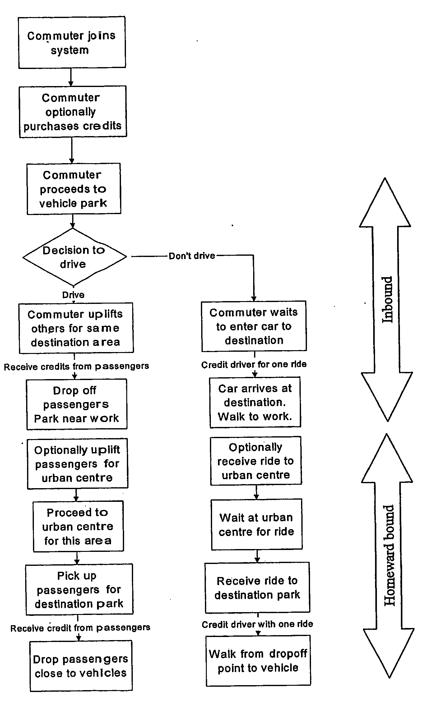
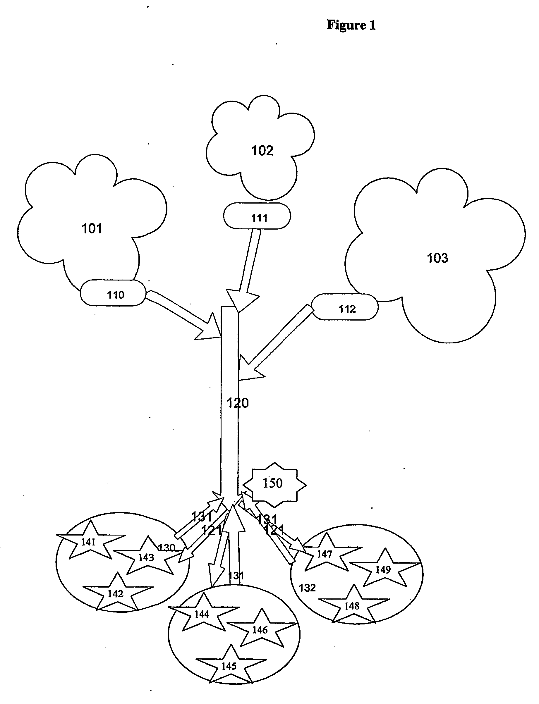
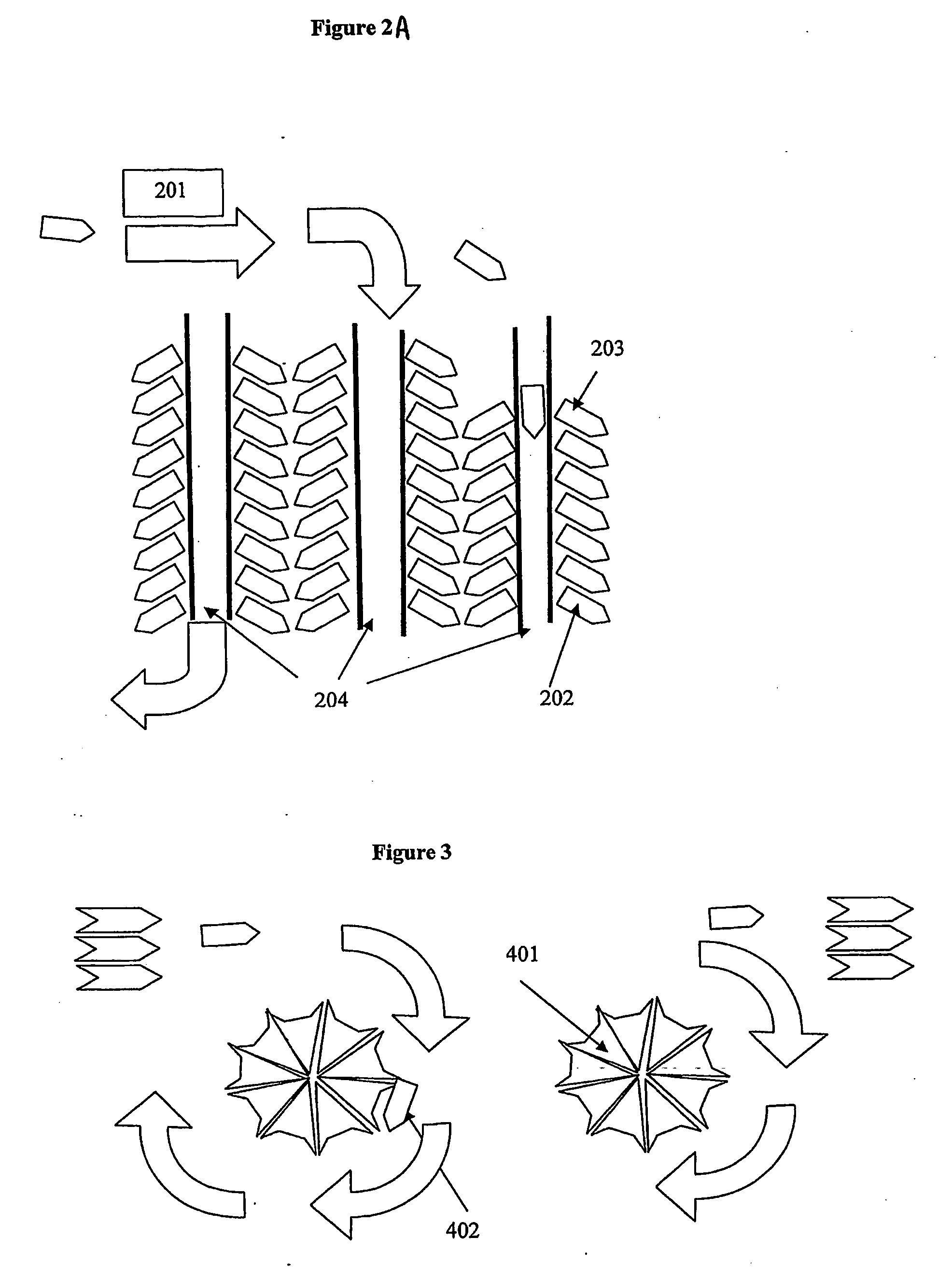
[0163] In FIG. 1 a commuter from one of areas 101, 102, 103 takes a vehicle to a vehicle park 110, 111, 112 as better shown in FIG. 2, and, decides to park his vehicle there. He makes a judgement about whether to drive or ride, and parks in a park beside a “drive through” lane to his chosen urban area and walks a few metres to the “drive through” lane where a driver who has opted to drive in to the urban area is either waiting for passengers or will shortly arrive.

[0164] The commuter is then transported by the driver who has opted to drive onto an arterial road, motorway or other route, 120 and via a route 121 to his desired urban area 130 and preferably dropped close to his ultimate destination.

[0165] An inducement will be the ability of drivers and their passengers to be favoured, as authorised participants of the scheme, to access [if allowed irrespective of fill or if appropriately filled] HOV lanes (e.g bus lanes in New Zealand).

[0166] After working the day, or at the end of...


PUM


Abstract

A transport system having commuters with identification and/or vehicles with identification (“identifiers”) authorising them to take part in the transport system, at least one vehicle park in which authorised commuters may park vehicles and/or take on board authorised commuters who may or may not have parked vehicles and transport them to a specified destination and/or for set down near the specified destination, a hub at which vehicles of authorised commuters or others may take on board authorised commuters and transport them to the or a said vehicle park, optionally near the specified destination, at least one pickup point from which authorised commuters may be transported back to the hub, and a benefit sharing system involving the use of the identifiers at the vehicle park(s) and/or said hub whereby an authorised commuter, when a driver of authorised commuter(s) leaving and/or returning to or arriving at the vehicle park(s) and/or hub, benefits at some detriment to each carried commuter.

Description

FIELD OF THE INVENTION [0001] This invention relates to a transport system utilising vehicle pooling, that is, a system whereby passengers whose routes converge share vehicles on a facilitated but not pre-committed basis. BACKGROUND OF THE INVENTION [0002] Commuter travel requirement leads to such congestion for many urban areas that local governments have now commenced using penalties to discourage commuters from using private cars. For example, the access charge in London, road tolls, petrol taxes etc. At the same time public bodies are using subsidies to encourage bus companies and the like to run uneconomic services. [0003] Typically transport systems use public transport to move commuters from a series of pickup locations to one of a series of destination locations. If commuters wish to go to a location which is not on the route taken by their chosen vehicle they must change en route to another vehicle having a different series of destinations. Such a system produces delays bot...

Claims


Application Information

Patent Timeline
Patent Type & Authority Applications(United States)
IPC IPC(8): G07B13/04G06F7/00
CPCG06Q10/02G06Q30/0284G06Q10/025
Inventor PEARCE, JOHN H.MINETT, PAUL
Owner PEARCE JOHN H
Why Eureka
Try Eureka