Storage device, computer system, and storage system

a storage device and computer system technology, applied in the field of storage devices, computer systems, and storage systems, can solve the problems of long erase time data cannot be overwritten, etc., and achieve the effect of remarkable drop in write efficiency

Active Publication Date: 2007-02-01
SONY CORP
View PDF11 Cites 65 Cited by
  • Summary
  • Abstract
  • Description
  • Claims
  • Application Information

AI Technical Summary

Benefits of technology

[0018] In recent years, flash memories have been looked at as promising alternatives to hard disk drives in terms of power consumption, seek time, impact resistance, portability, etc. However, as explained above, it is difficut to increas in speed of flash memories unless making the access units larger. Further, data cannot be overwritten. Therefore, re

Problems solved by technology

However, as explained above, it is difficut to increas in speed of flash memories unless making the access units larger.
Further, data cannot be overwritten.
This results in a long eras

Method used


Image

  • Storage device, computer system, and storage system
  • Storage device, computer system, and storage system
  • Storage device, computer system, and storage system

Examples


first embodiment

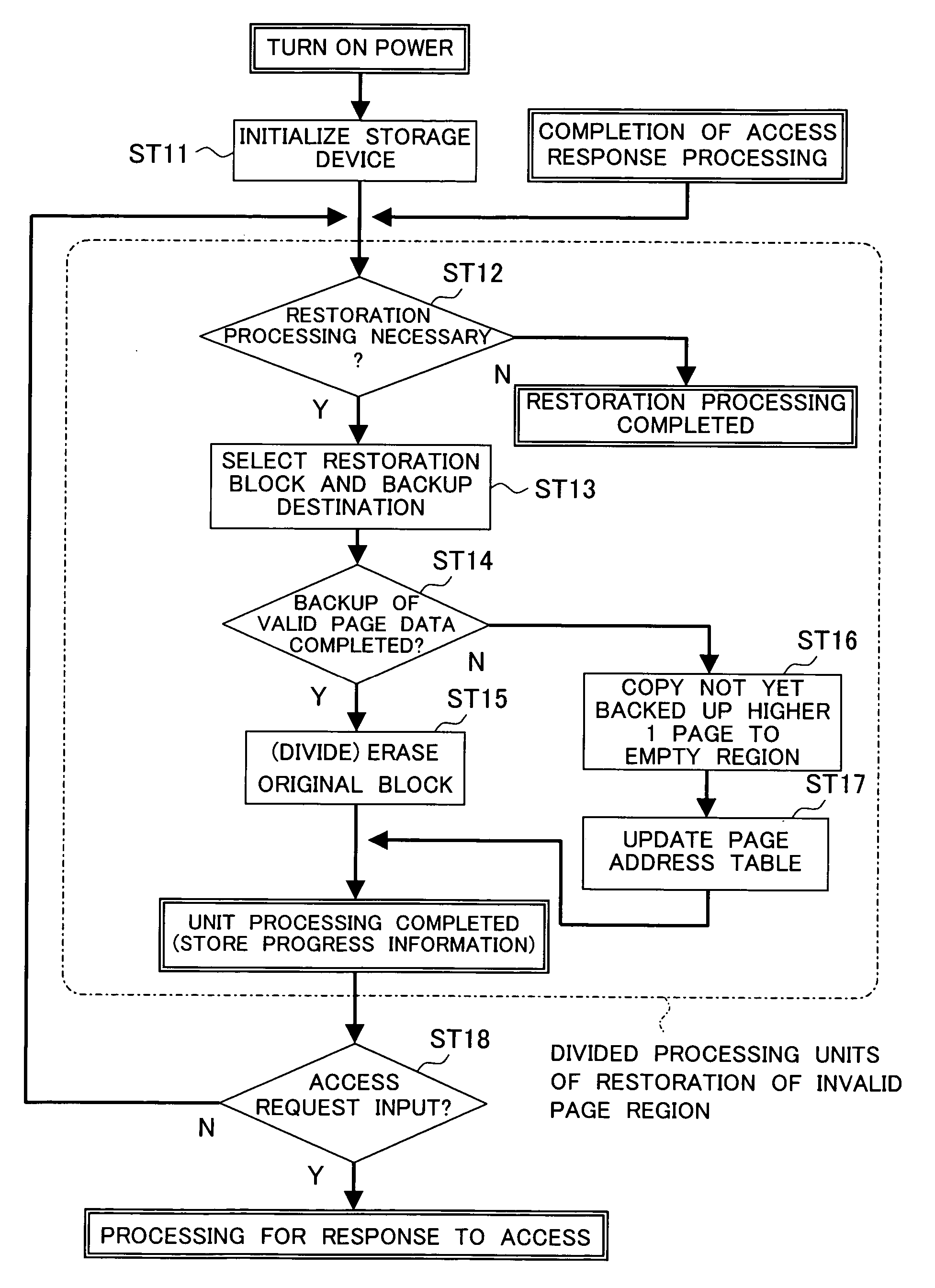
[0118] Here, the present invention provides the semiconductor memory device employing an additional rewritting type write operation into a flash memory described above with a mechanism for automatically executing the restoration processing of the regions invalidated at the standby time.

[0119] The “standby time” referred here is for example a state after the power of the storage device is turned on, the initialization work ends, and access is possible at any time, but there is no access request from the outside. In actuality, a file storage system such as a hard disk drive is not accessed from the outside all the time. The standby state is rather longer. Alternatively, even in the case where the storage device is seemingly continuously accessed such as when recording a video image, if the average rate of transfer of the data input from the host computer to the storage device is sufficiently smaller than the data transfer capability of the storage device itself, in actuality, the host...

second embodiment

[0156]FIG. 10 is a flow chart for explaining the restoration processing according to the

[0157] In the first embodiment, the restoration processing was automatically executed when the device entered into the standby state, but in the second embodiment, the restoration processing is executed according to a restoration command input from outside of the device. In the figure, the restoration processing ST21 to ST26 of the invalid page regions indicated by a broken line in the figure are the same as the processing (tasks) ST2 to ST7 of FIG. 8 in the first embodiment.

[0158] Further, the second embodiment has a function of interrupting the restoration processing in response to a predetermined command from the user. For example, when it is an access command to the data, the processing for response to the access is carried out, while when it is an command for only interrupting the restoration processing, the device is shifted to the access standby state. The access command, the start comman...

third embodiment

[0173] When the host computer accesses the storage device 110 again and tries to access the data of the same logical address as that stored in the cache memory 117, the data on the cache memory 117 side is accessed. Accordingly, during this period, none of the page buffer 112, internal data bus 113, and NAND type flash memories 115 and 116 is used for access. In the third embodiment, this period is therefore utilized for the restoration processing of invalid page regions.

[0174]FIG. 14 is a flow chart for explaining the restoration processing according to the third embodiment. In the figure, the restoration processing of invalid page regions indicated by the broken line is the same as the processing (tasks) ST2 to ST7 of FIG. 8 in the first embodiment.

[0175] In this example, in the same way as the first embodiment, the restoration processing is automatically executed when the device enters into the standby state, but the time when the restoration processing is interrupted due to an ...


PUM


Abstract

A storage device enabling realization of a new storage configuration enabling apparent elimination of the overhead and enabling high speed access all the time particularly when constructing a high parallel configured high speed flash memory system, that is, a storage device having a flash memory as a main storage and having the function of rewriting at least a partial region of the flash memory by additional writing update data in an empty region and invalidating original data and, at the time of standby of the device where there is no access from the outside, performing processing for automatically restoring the invalidated region to an empty region, and a computer system and a storage system using the same.

Description

CROSS REFERENCE TO RELATED APPLICATION [0001] The present invention contains subject matter related to Japanese Patent Application No. 2005-221714 filed in the Japan Patent Office on Jul. 29, 2005, and Japanese Patent Application No. 2006-137844 filed in the Japan Patent Office on May 17, 2006 the entire contents of which being incorporated herein by reference. BACKGROUND OF THE INVENTION [0002] 1. Field of Invention [0003] The present invention relates to a storage device including a nonvolatile memory and a computer system and a storage system provided with same, more particularly relates to an increase of speed of data transfer in a storage device including a flash memory. [0004] 2. Description of the Related Art [0005] In recent years, flash memories are coming into attention as storage media of digital still cameras and portable computer devices. [0006] A flash memory is a semiconductor memory using tunneling or hot electron acceleration to cause electrons to pass through a gat...

Claims


Application Information

Patent Timeline
IPC IPC(8): G06F12/00G06F13/00
CPCG06F12/0246G06F2212/7205G06F12/00G06F12/16
Inventor NISHIHARA, TOSHIYUKI
Owner SONY CORP
Why Eureka
Try Eureka