Shift position sensor of automated manual transmission

Active Publication Date: 2007-02-08
NISSAN MOTOR CO LTD
View PDF9 Cites 30 Cited by
  • Summary
  • Abstract
  • Description
  • Claims
  • Application Information

AI Technical Summary

Problems solved by technology

However, due to inherent construction, the above-mentioned shift position sensor fails to have an easiness with which the sensor can be mounted to a proper position of the transmission.
Furthermore, it sometimes occurs that the sensor bra

Method used


Image

  • Shift position sensor of automated manual transmission
  • Shift position sensor of automated manual transmission
  • Shift position sensor of automated manual transmission

Examples


first embodiment

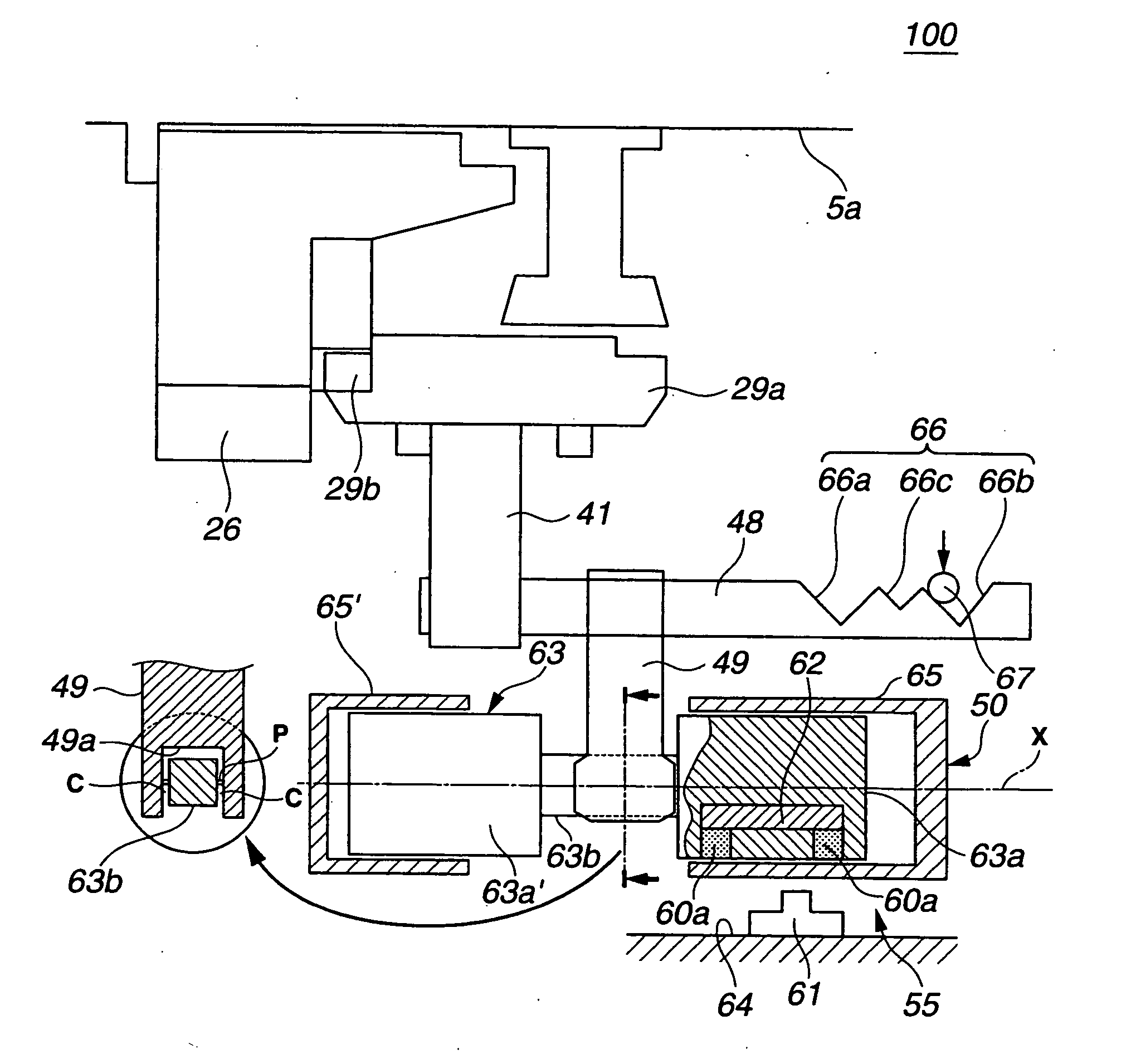
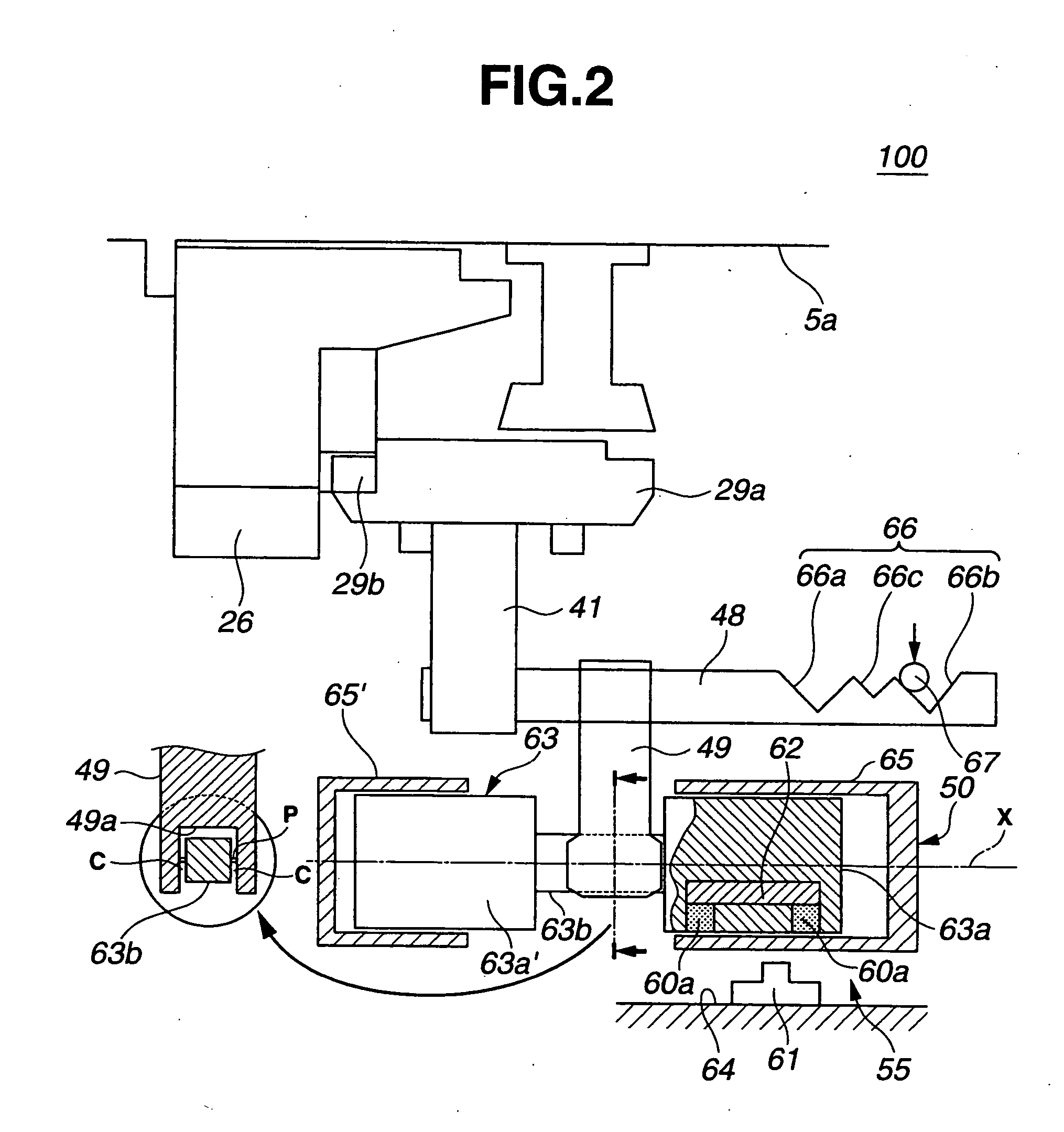
[0117] Because of the above-mentioned constructional features, the following advantages are provided by the shift position sensor 100 of the present invention.

[0118] First, since magnets 60a and 60a are fully embedded in piston portion 63a of piston unit 63, the stability and durability of the same are improved.

[0119] Second, since piston unit 63 that has the two magnets 60a and 60a embedded therein and actuator unit case 64 that has magnaflux detector 61 mounted thereon are mutually adjacent members that are installed in actuator unit 45, the work for making a mutual positioning between two magnets 60a and 60a and magnaflux detector 61 is easily carried out. The work is much facilitated when actuator unit case 64 and cylinders 65 and 65′ are integrally formed. When actuator unit case 64 and cylinders 65 and 65′ are integrally formed, an accurate positioning between magnets 60a and 60a and magnaflux detector 61 is easily achieved by only placing or mounting magnaflux detector 61 to...

second embodiment

[0124] Referring to FIG. 6, there is shown a sectional view similar to FIG. 4B, but which shows an essential portion of a shift position sensor 200 of the present invention.

embodiment 200

[0125] As is seen from this drawing, in this embodiment 200, each magnet 60b has an arc-shaped cross section and an even thickness throughout the entire structure thereof, and is evenly magnetized in substantially straight direction.

[0126] In this second embodiment 200, the length of inside concave part “i” and that of outside convex part “o” are substantially the same.

[0127] In this second embodiment 200, in addition to the advantages possessed by the above-mentioned first embodiment 100, the following advantage is further obtained.

[0128] That is, it is easy to produce magnets 60b because of the magnetization in the straight direction. Actually, for the production of magnets 60b, at first, a large block of material is magnetized and then the magnetized block is cut into a plurality of pieces, viz., the magnets 60b. As is easily understood, such production method brings about a low cost product of the shift position sensor 200.


PUM


Abstract

An automated manual transmission to which a shift position sensor of the present invention is practically applied has a hydraulic shift actuator that includes a cylinder and a piston that moves in the cylinder in accordance with a speed change operation of the transmission. The shift position sensor comprises a magnet mounted in the piston to move therewith, and a magnaflux detector mounted to a fixed member of the transmission near the hydraulic shift actuator to detect a magnaflux produced by the magnet. The cylinder is so constructed as to cover the magnet even when the piston is subjected to a stroke in the cylinder.

Description

BACKGROUND OF THE INVENTION [0001] 1. Field of the Invention [0002] The present invention relates in general to automated manual transmissions, viz., automotive manual transmissions of an automatic speed change type that includes a plurality of shift forks, a first clutch used for establishing odd number speeds, a second clutch used for establishing even number speeds and a plurality of hydraulic shift actuators for actuating the shift forks respectively. More specifically, the present invention is concerned with a shift position sensor of such automated manual transmissions, which senses a shift position that is actually taken by the transmission. [0003] 2. Description of the Related Art [0004] In order to clarify the task of the present invention, one known automated manual transmission will be briefly described, which is disclosed in Japanese Laid-open Patent Application (Tokkaihei) 8-320054. [0005] The transmission disclosed in the Patent Application is of a twin clutch type tha...

Claims


Application Information

Patent Timeline
IPC IPC(8): F16H61/00
CPCF16H59/70Y10T74/19251F16H2063/303F16H63/3023G01D5/145
Inventor FUTAMURA, MAKOTOKITOU, MASASUMI
Owner NISSAN MOTOR CO LTD
Why Eureka
Try Eureka