
Double clutch transmission for a hybrid electric vehicle and method for operating the same

a hybrid electric vehicle and transmission technology, applied in the direction of battery/fuel cell control arrangement, vehicle sub-unit features, gearing, etc., can solve the problems of cvt requiring very high hydraulic pressure for operation, hev cannot always operate the engine at the optimal operating point, and series hevs are less energy efficient than parallel hevs

Inactive Publication Date: 2007-02-08
HYUNDAI MOTOR CO LTD
View PDF7 Cites 48 Cited by
  • Summary
  • Abstract
  • Description
  • Claims
  • Application Information

AI Technical Summary

Benefits of technology

The present invention provides a double clutch transmission for a hybrid electric vehicle that can change torque of the engine and motor quickly and output it to the wheels. The transmission has two input shafts, two clutches, and a differential gear. The first output device has two output shafts and a plurality of driven gears, while the second output device has a reverse idle shaft and a plurality of driven gears, a reverse driven gear, and a plurality of mediating gears. The motor input / output unit selectively transmits torque of the motor to the second input shaft. The method for controlling the double clutch transmission includes determining the operation mode and controlling the transmission accordingly. The technical effects of the invention include improved efficiency, better torque output, and improved vehicle performance.

Problems solved by technology

However, series HEVs are less energy efficient than parallel HEVs because energy in series HEVs is first converted from mechanical energy of an engine into electrical energy in a battery, and then used for running a motor.
However, a parallel HEV cannot always operate the engine at an optimal operating point since the engine and the motor are mechanically coupled together through a transmission and the engine speed is correlated with the vehicle speed.
However, such a CVT requires very high hydraulic pressure for operation in comparison with other transmissions such as an automatic transmission.
Therefore, in spite of various functionally favorable features, a CVT does not manifest particularly substantial energy efficiency.

Method used


Image

  • Double clutch transmission for a hybrid electric vehicle and method for operating the same
  • Double clutch transmission for a hybrid electric vehicle and method for operating the same
  • Double clutch transmission for a hybrid electric vehicle and method for operating the same

Examples


Embodiment Construction

[0037] An embodiment of the present invention will hereinafter be described in detail with reference to the accompanying drawings.

[0038] As is well known in the art, a double clutch transmission (DCT) includes two clutch devices within a transmission scheme that is similar to a manual transmission. In a DCT, torque from an engine is transmitted to two input shafts through two clutches, and is then changed and output using gears disposed on the two input shafts.

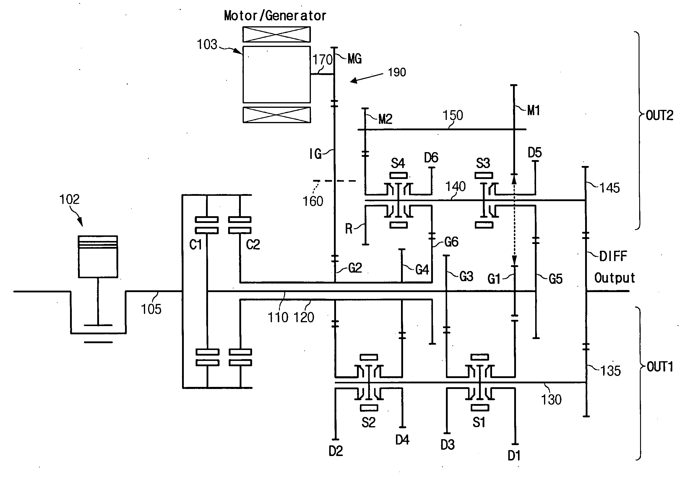
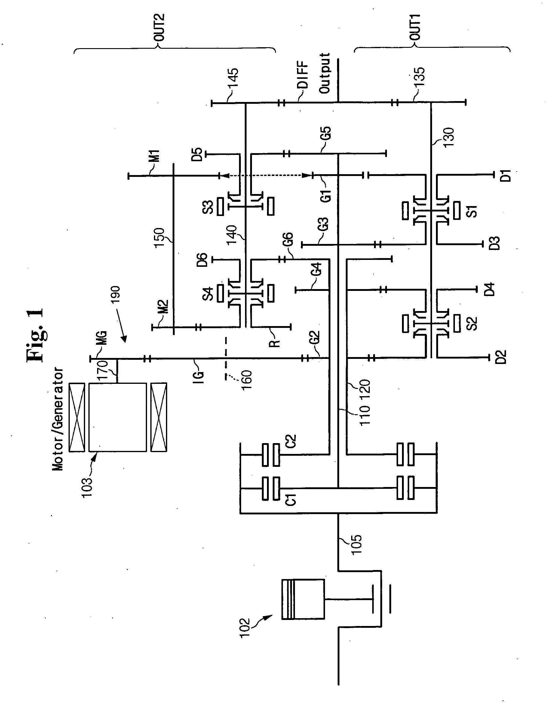
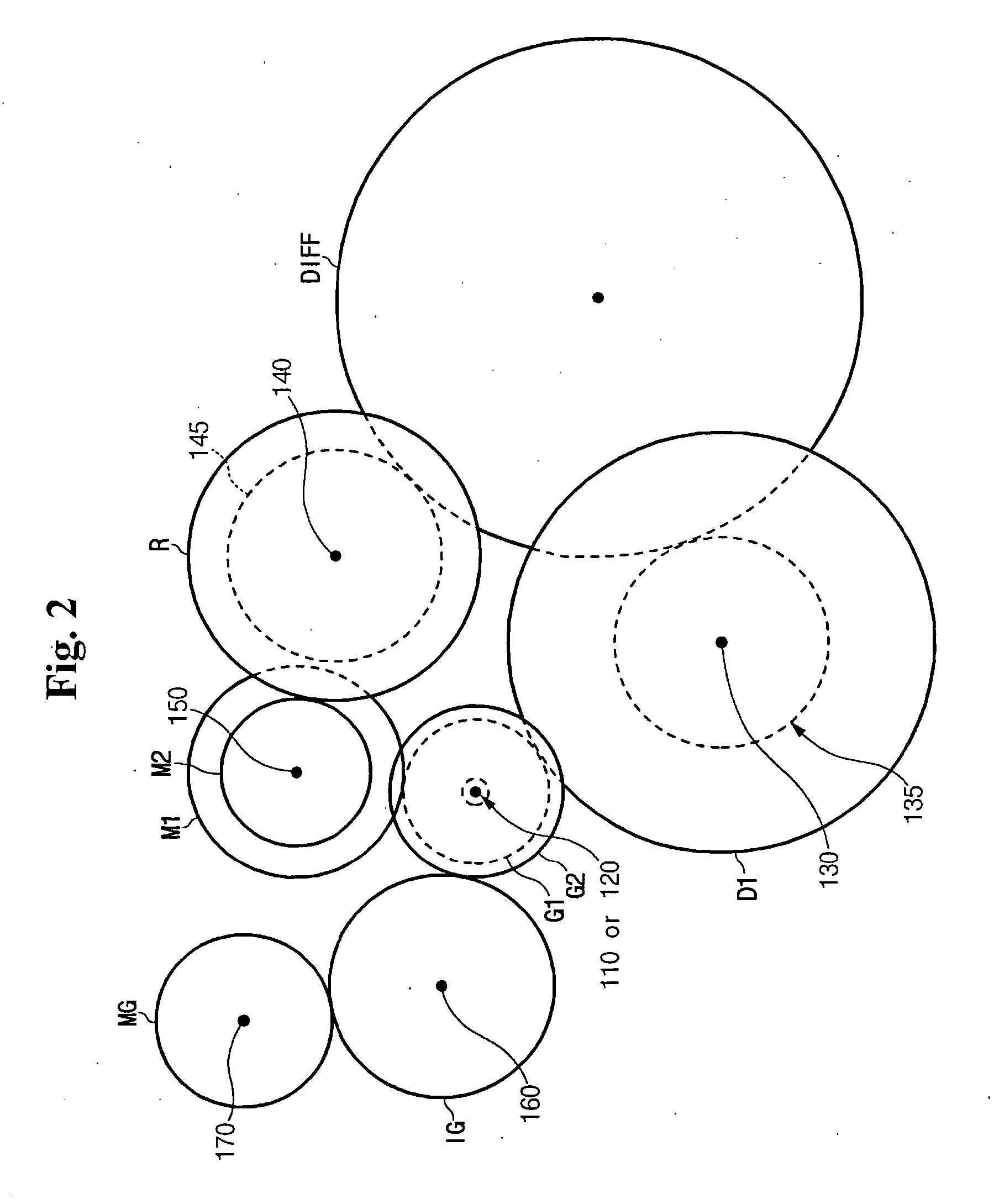
[0039] An embodiment of the present invention applies such a DCT to a hybrid electric vehicle (HEV) having two power sources of an engine and a motor. FIG. 1 is a schematic diagram of a DCT for an HEV according to an embodiment of the present invention, and FIG. 2 is a drawing illustrating a disposition relationship among first and second input shafts, first and second output shafts, a reverse idle shaft, a differential gear, and a motor gear of a DCT for an HEV according to an embodiment of the present invention.

[0040] As ...


PUM


Abstract

A double clutch transmission is described that ideally changes torque received from an engine and a motor by providing an optimal layout in power transmission scheme and motor location. Such a double clutch transmission is optimally adapted to a hybrid electric vehicle, and an optimal operation method for such a double clutch transmission is also provided, overcoming inefficiency in application of a conventional CVT to an HEV.

Description

CROSS REFERENCE TO RELATED APPLICATION [0001] This application claims priority to Korean Application No. 10-2003-0096568, filed on Dec. 24, 2003, the content of which is incorporated herein by reference. FIELD OF THE INVENTION [0002] The present invention relates to a double clutch transmission for a hybrid electric vehicle, and a method for operating the same. BACKGROUND OF THE INVENTION [0003] Generally, “hybrid vehicle” is a vehicle utilizing a plurality of power sources, and usually refers to a hybrid electric vehicle (HEV) that is driven by an engine and a motor. HEVs may be realized in various schemes adopting an engine and a motor, and a majority of schemes are based on a parallel construction or a series construction. [0004] A series scheme is simpler in structure than a parallel scheme, so it is easier to control. However, series HEVs are less energy efficient than parallel HEVs because energy in series HEVs is first converted from mechanical energy of an engine into electr...

Claims


Application Information

Patent Timeline
Patent Type & Authority Applications(United States)
IPC IPC(8): F16H37/06B60K6/36B60K6/365B60K6/38B60K6/387B60K6/40B60K6/48B60K6/547B60K17/04B60W10/02B60W10/10B60W20/00F16H3/00F16H3/08F16H3/083F16H3/44F16H59/74F16H61/02F16H61/26F16H61/68F16H61/682F16H63/50
CPCB60K6/36Y10T477/23B60K6/48B60K6/547B60W10/02B60W10/06B60W10/08B60W10/113B60W20/00B60W2510/244B60Y2400/428F16H3/006F16H2003/0931Y02T10/6221Y02T10/6286B60L7/12B60L11/14B60L11/1861B60L15/2009B60L15/2054B60L2240/12B60L2240/421B60L2240/423B60L2240/441B60L2240/443B60L2250/26Y10T74/19014B60K6/387Y02T10/70Y02T10/72B60L50/16B60L58/12Y02T10/62Y02T10/64Y02T10/7072B60K2006/4825F16H3/44
Inventor LEE, HEE RAKIM, CHUL SOOKIM, TAL CHOL
Owner HYUNDAI MOTOR CO LTD
Learn More