

Optical network system and transmission apparatus
- Summary
- Abstract
- Description
- Claims
- Application Information
AI Technical Summary
Benefits of technology
Problems solved by technology
Method used
Image

Examples
first embodiment
[A1] First Embodiment
[0051] [A1-1] Configuration
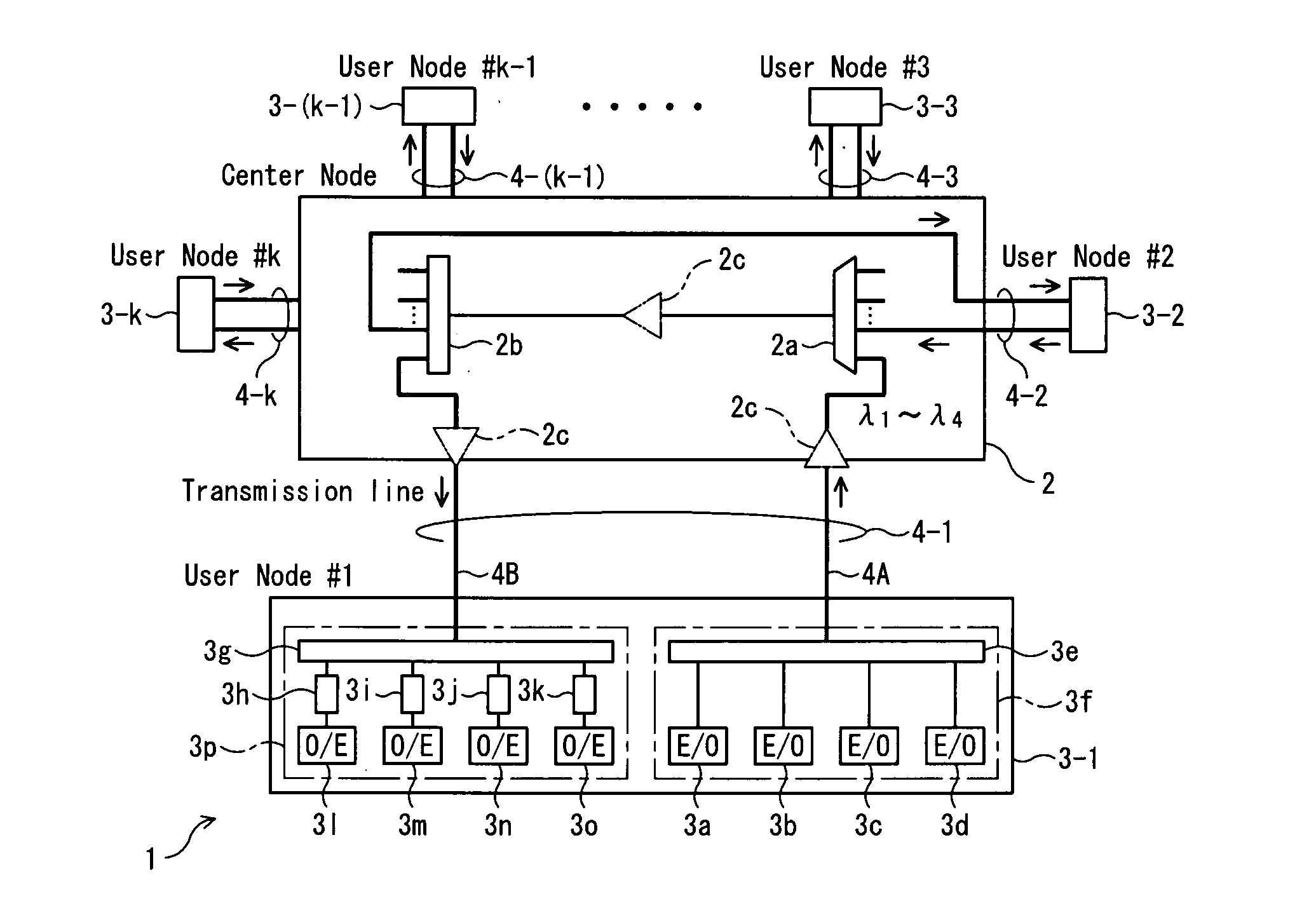
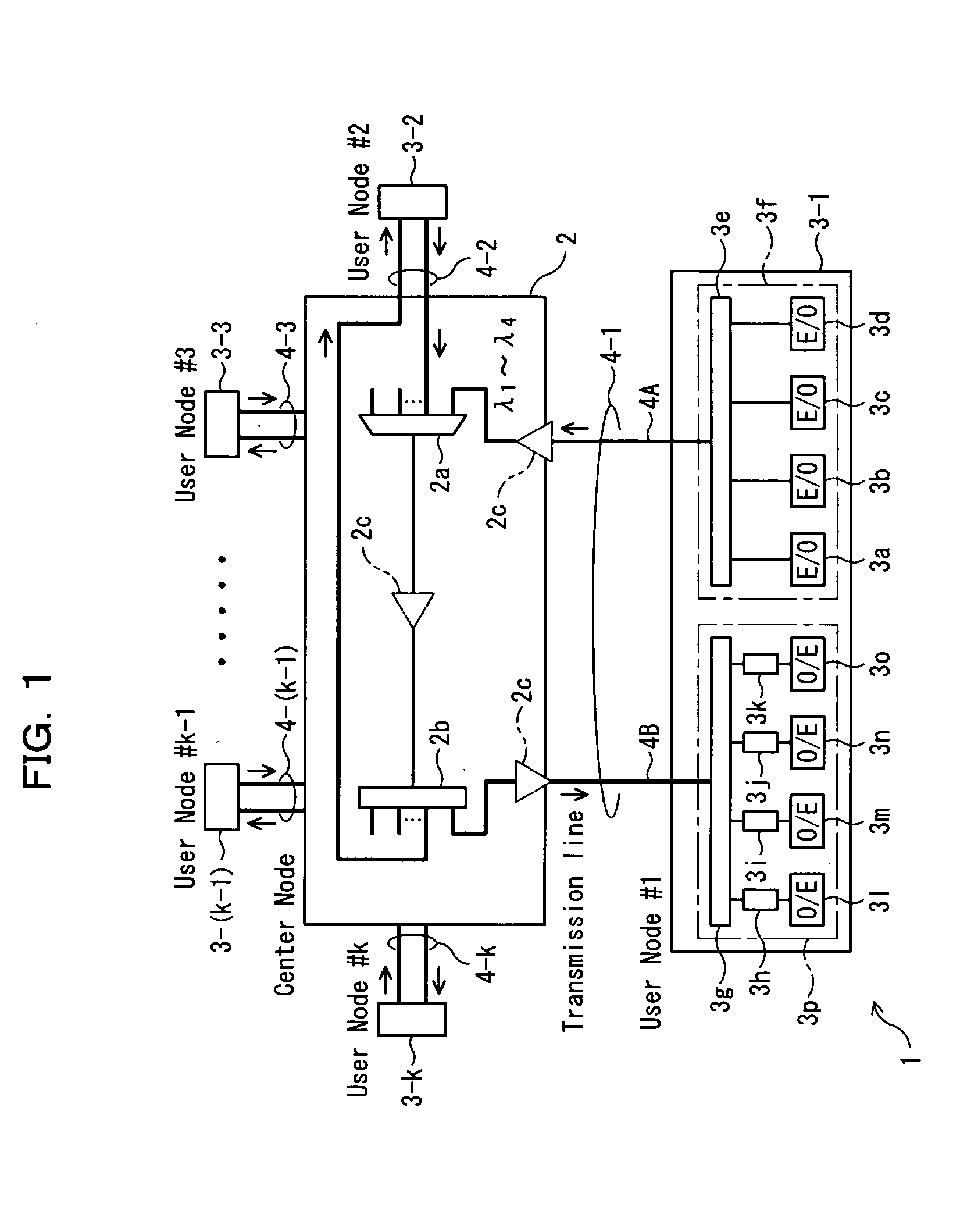
[0052]FIG. 1 is a block diagram showing an optical network system 1 according to a first embodiment of the present invention. Referring to FIG. 1, the optical network system 1 shown includes a central node 2 which is a transmission apparatus, a plurality of user nodes (User Node #1 to #k) 3-1 to 3-k which are transmission apparatus connected to the central node 2 through transmission lines 4-1 to 4-k, respectively, and transmits and receives optical signals between the user nodes 3-1 to 3-k (k is a plural number and is, in this instance, 5 or more) through the central node 2.
[0053] In particular, the optical network system 1 can be formed not only in star-shaped network topology wherein the user nodes 3-1 to 3-k are connected radially from the central node 2 and but also in tree-shaped network topology wherein signals can be distributed from a specific user node (for example, user node 3-1) to the other user nodes (for example, user ...
second embodiment
[B1] Second Embodiment
[0110] [B1-1] Configuration
[0111]FIG. 6 is a block diagram showing an optical network system 101 according to a second embodiment of the present invention. The optical network system 101 shown in FIG. 6 is similar in configuration of user nodes 3-1 to 3-k and transmission lines 4-1 to 4-k to but is different in configuration of a central node 102 from the optical network system 1 described hereinabove with reference to FIG. 1.
[0112] The optical network system 101 includes a ring transmission line 102a, and branching / insertion sections 102f-1 to 102f-k provided corresponding to the user nodes 3-1 to 3-k, respectively. The branching / insertion sections 102f-1 to 102f-k include reject / add filters 102b-1 to 102b-k and central node side branching sections 102c-1 to 102c-k, respectively.
[0113] The reject / add filters 102b-1 to 102b-k are optical filters each having a function as a central node side multiplexing section for multiplexing (adding) optical signals trans...
third embodiment
[C1] Third Embodiment
[0146] [C1-1] Configuration
[0147]FIG. 11 shows an optical network system 201 according to a third embodiment of the present invention. The optical network system 201 shown in FIG. 11 is different from the optical network system 1 of the first embodiment described hereinabove in that optical wavelengths to be extracted as reception signals in user nodes 203-1 to 203-k are fixed and, for example, four different wavelengths which can be set variably are used as transmission wavelengths.
[0148] To this end, the optical network system 201 includes a central node 202 and user nodes 203-1 to 203-k having configurations different from those in the first embodiment and further includes a management apparatus 204 for managing the transmission wavelengths to be variably selected in the user nodes 203-1 to 203-k. It is to be noted that transmission lines 4-1 to 4-k for connecting the central node 202 and the user nodes 203-1 to 203-k to each other are similar to those in t...
PUM
 Abstract
Description
Claims
Application Information