Electronic apparatus

a technology of electronic equipment and mask rom, applied in the field of electronic equipment, can solve the problems of delay of a due date, cost increase, program and data regarding a power control method stored in the mask rom of the auxiliary microprocessor, etc., and achieve the effect of reducing the cost increas

Inactive Publication Date: 2007-02-08
FUNAI ELECTRIC CO LTD
View PDF4 Cites 8 Cited by
  • Summary
  • Abstract
  • Description
  • Claims
  • Application Information

AI Technical Summary

Benefits of technology

[0010] According to such a constitution, the auxiliary micro processor controls the electric power supply by the power control method which is indicated by the power control data transmitted from the main micro processor, so that the power control method of the auxiliary micro processor can be changed with changing contents of the power control data transmitted from the main micro processor. Accordingly, in case that the power control method needs to be changed due to, for example, the problem of a circuit board, the power control method can be changed by changing the contents of the power control data transmitted from the main micro processor instead of ordering the auxiliary micro processor having the mask ROM system, and the chance of the delay of the due date or the cost increase can be reduced.

Problems solved by technology

However, with regard to the conventional electronic apparatuses described above, since the auxiliary micro processor is constituted to have a mask ROM system, a program and data regarding a power control method stored in the mask ROM of the auxiliary micro processor cannot be rewritten.
For this reason, in case that the power control method needs to be changed due to a problem that a main micro processor and peripheral devices do not function well when a power source is supplied to them, the auxiliary micro processor having the mask ROM system has to be remade every time, thus a problem such as a delay of a due date or a cost increase arises.

Method used


Image

  • Electronic apparatus
  • Electronic apparatus
  • Electronic apparatus

Examples


Embodiment Construction

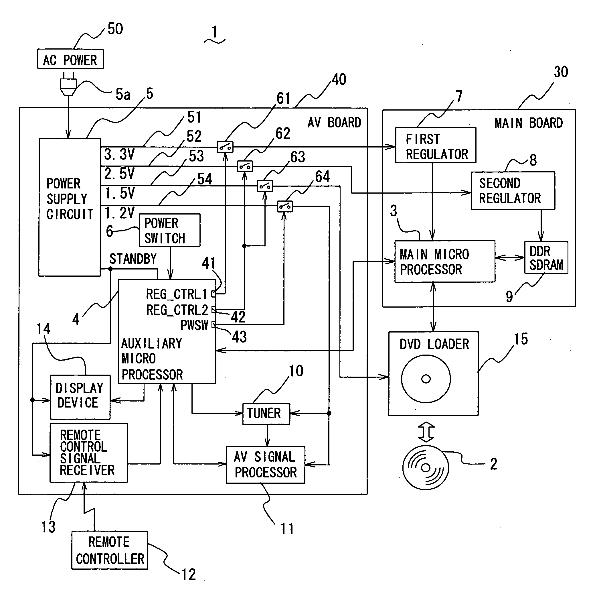
[0016] An electronic apparatus in accordance with an embodiment of the present invention is described with reference to the drawings. FIG. 1 shows a constitution of a DVD (Digital Versatile Disc) recorder 1, which is an example of the electronic apparatus. The DVD recorder 1 receives TV (Television) broadcast signals from broadcast stations, stores video data, audio data, and so on delivered with the TV broadcast signals into a DVD 2, and reproduces the video data, the audio data, and so on stored in the DVD 2 through a display and a speaker not shown in the drawings.

[0017] The DVD recorder 1 comprises a main micro processor 3 and a auxiliary micro processor 4 to control the DVD recorder 1, a power supply circuit 5 generating an electric power for driving the DVD recorder 1, a power switch 6 for activating or inactivating the DVD recorder 1, a first regulator 7, a second regulator 8, a DDRSDRAM (Double Data Rate Synchronous Dynamic Random Access Memory) 9, a tuner 10, an AV signal ...


PUM

PropertyMeasurementUnit
voltagesaaaaaaaaaa
voltagesaaaaaaaaaa
voltagesaaaaaaaaaa

Abstract

In an electronic apparatus such as a DVD recorder (1) which controls electric power supply to a main micro processor (3) and peripheral devices (10, 11, 15) with a auxiliary micro processor (4), a power control method by the auxiliary micro processor (4) can be changed. The main micro processor (3) transmits a power control data, which indicates a control method of the electric power supply, to the auxiliary micro processor (4). The auxiliary micro processor (4) controls the electric power supply by a method indicated by the power control data. Contents of the power control data is composed of sixteen bits data, and each four bits data as a unit indicate a control method of a power control terminal “REG_CTRL 1” (41) during a switching off operation of a power switch (6), a control method of the power control terminal “REG_CTRL 1” (41) during a switching off operation of the power switch (6), a control method of a power control terminal “PWSW” (43) during the switching off operation of the power switch (6), and a control method of the power control terminal “PWSW” (43) during the switching on operation of the power switch (6).

Description

BACKGROUND OF THE INVENTION [0001] 1. Field of the Invention [0002] The present invention relates to an electronic apparatus comprising a main micro processor and an auxiliary micro processor and controlling an electric power supply to the main micro processor and peripheral devices through the auxiliary micro processor. [0003] 2. Description of the Related Art [0004] With regard to an electronic apparatus such as a DVD recorder comprising a main micro processor and an auxiliary micro processor, it is conventionally known that the auxiliary micro processor controls electric power supply to the main micro processor and peripheral devices. In such an electronic apparatus, a program and data relating to a power control method for controlling the electric power supply are stored in a mask ROM (Read Only Memory) in the auxiliary micro processor, and the auxiliary micro processor controls the electric power supply to the main micro processor and the peripheral devices based on the program...

Claims


Application Information

Patent Timeline
Patent Type & Authority Applications(United States)
IPC IPC(8): B23K11/24
CPCG11B33/12G11B33/06
Inventor WATANABE, SATOMI
Owner FUNAI ELECTRIC CO LTD
Why Eureka
Try Eureka