APPARATUS OF LIGHT SOURCE AND ADJUSTABLE CONTROL CIRCUIT FOR LEDs

a control circuit and led technology, applied in the field of led light source and adjustable control circuit, can solve the problems of beating interference generated by vertical and horizontal scanning signals, water ripples on video images, and the problem of using led as the light source for lcd backlight or general lighting system becomes problematic, and achieves the effect of reducing the visual noise interference generated by beam density light adjustmen

Inactive Publication Date: 2007-02-08
BEYOND INNOVATION TECH
View PDF7 Cites 109 Cited by
  • Summary
  • Abstract
  • Description
  • Claims
  • Application Information

AI Technical Summary

Benefits of technology

[0011] Based on the above, the object of the present invention is to provide a low visual noise beam density light adjusting control circuit used in having a plurality of LEDs as the light source. More specifically, the light source includes the LEDs with different colors. Through controlling the brightness of each LED, the phase of pulse signal is controlled, thus the visual noise interference generated by beam density light adjustment is reduced.

Problems solved by technology

Thus, using LED as the light source for the LCD backlight or general lighting system becomes problematic in the application of light adjustment through adjusting the LED driving DC directly.
Since the frequency and the working cycle of the brightness control pulse signal CNTL used in the above description are set based on the required brightness, therefore once the brightness is adjusted, using the frequency of the brightness control pulse signal CNTL in LCD backlight may encounter the beat interference problem generated by the vertical and horizontal scanning signals in the video display signal.
Because the backlight and the video signals have different frequencies that causes the so-called “fan effect”, so that results in water ripples on the video images.
These ripples may also affect the video display signal and result in flickering images.
In the circumstance of using more LEDs as the light source, the interference caused by the adjustment of the beam density may become severer as the LED operation power increases.
However, in the trend that the LCD size is getting bigger and bigger, more and more LEDs are used, and the power consumption is getting larger and larger, and in the circumstance of the requirement for reducing visual noise is getting stricter, it becomes more and more difficult to keep low noise, light adjustment of wide range in practical mass production.

Method used


Image

  • APPARATUS OF LIGHT SOURCE AND ADJUSTABLE CONTROL CIRCUIT FOR LEDs
  • APPARATUS OF LIGHT SOURCE AND ADJUSTABLE CONTROL CIRCUIT FOR LEDs
  • APPARATUS OF LIGHT SOURCE AND ADJUSTABLE CONTROL CIRCUIT FOR LEDs

Examples


Embodiment Construction

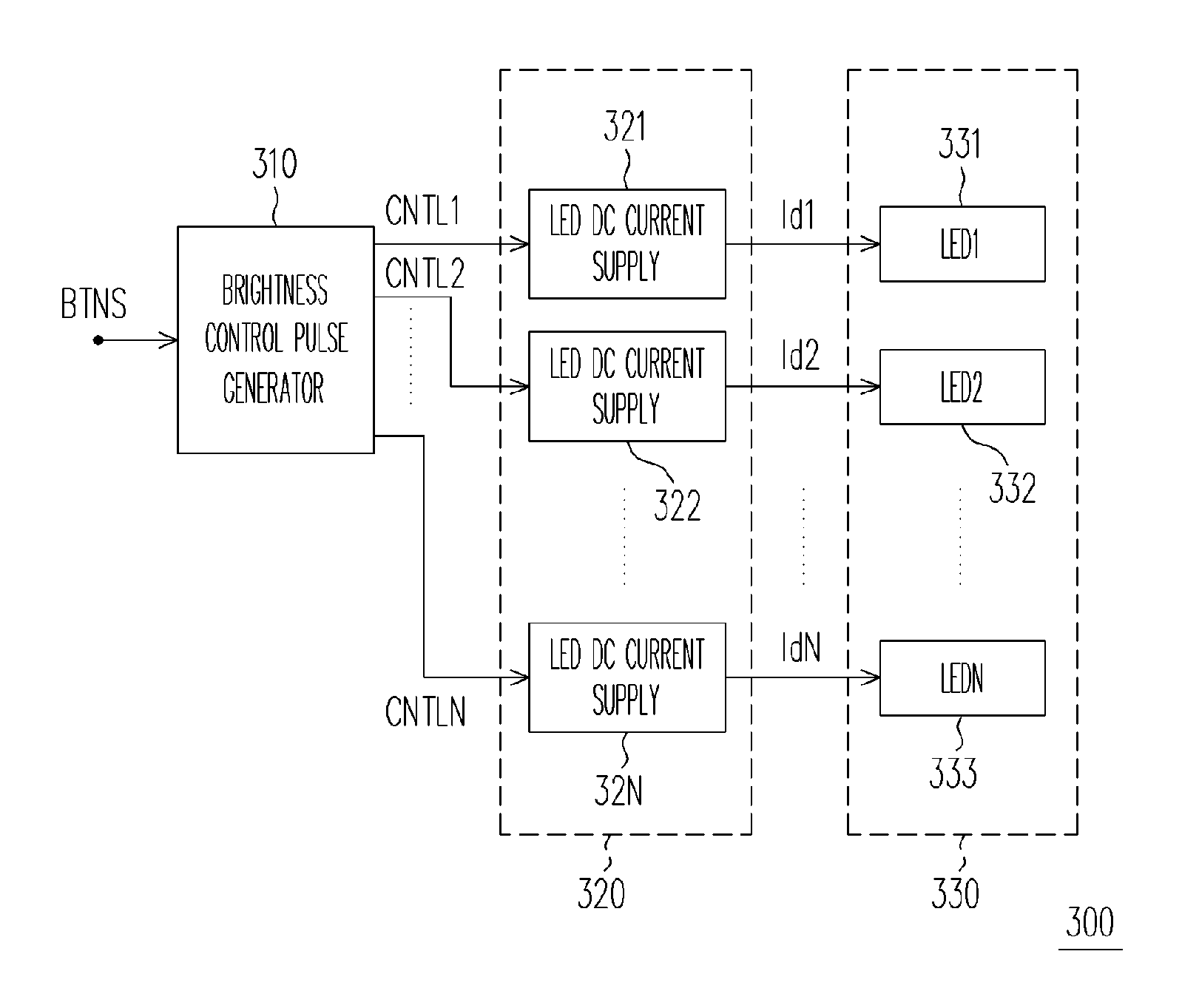
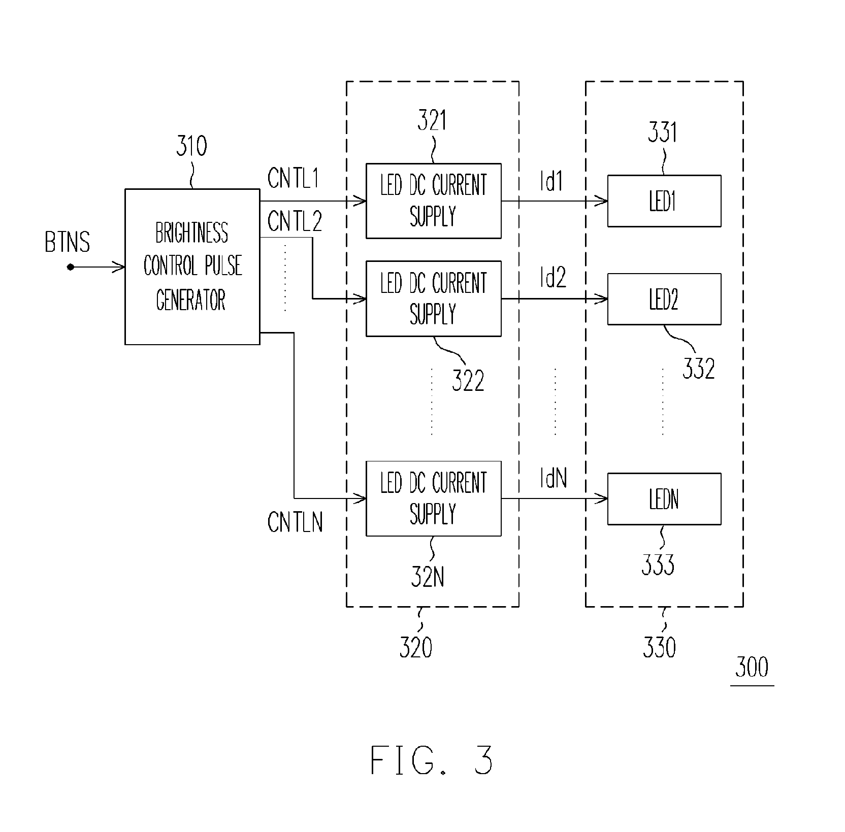
[0025] With reference to FIG. 3, FIG. 3 is a schematic block diagram of a low visual noise beam density light adjusting control circuit according to the embodiment of the present invention. The low visual noise beam density light adjusting control circuit 300 is suitable for controlling the brightness of plural groups of LEDs 330 in an LCD.

[0026] As shown in FIG. 3, the low visual noise beam density light adjusting control circuit 300 includes a brightness control pulse generator 310, an LED DC current supply unit 320 and LEDs 330. Wherein, the brightness control pulse generator 310 is used to receive the brightness adjusting signal BTNS and generate plural groups of brightness control pulse signals within a predetermined range according to the brightness adjusting signal BTNS. And wherein there could be least two of the phases of the control pulse signals CNTL1, CNTL2, . . . , CNTLN are different, or the phases of the control pulse signals CNTL1, CNTL2, . . . CNTLN could be all di...


PUM


Abstract

A control circuit for LEDs is adapted for controlling brightness of a plurality of LEDs as light source in an LCD. The control circuit comprises a control pulse generator and a plurality of LED direct current supplies. The control pulse generator is used for receiving a brightness adjusting signal and generating a plurality of brightness control pulse signals having the same frequency but different phases according to the brightness control signals. The work cycle of the brightness control pulse signal varies in a predetermined range according to the brightness control signal. The LED direct current provider is coupled to the control pulse generator to drive the corresponding LED according to the brightness pulse signal.

Description

CROSS-REFERENCE TO RELATED APPLICATION [0001] This application claims the priority benefit of Taiwan application serial no. 94126315, filed on Aug. 3, 2005. All disclosure of the Taiwan application is incorporated herein by reference. BACKGROUND OF THE INVENTION [0002] 1. Field of Invention [0003] The present invention relates to a light adjustable control circuit, which is directed to a beam density adjustment control circuit using a plurality of LEDs as the light source. More specifically, the present invention relates to a beam density adjustment control circuit using a plurality of LEDs with different colors as the light source. [0004] 2. Description of Related Art [0005] Using an LED as the light source, simply utilizing direct current (DC) driving circuit can realize the demand for the LCD backlight or general lighting system. Due to the characteristics, The relationship between the LCD brightness and the driving DC is non-linear, and the LCD color may also vary with the chang...

Claims


Application Information

Patent Timeline
Patent Type & Authority Applications(United States)
IPC IPC(8): H05B41/36
CPCH05B33/0857H05B33/0818H05B45/20
Inventor YU, CHUNG-CHELEE, LI MIN
Owner BEYOND INNOVATION TECH
Why Eureka
Try Eureka