Antenna Structure

a technology of antennas and antennas, applied in the field of antennas, can solve the problems of inability to integrate multiple frequencies for transmitting and receiving radio signals, and the inability to meet the compact size requirements of the information industry

Active Publication Date: 2007-02-08
WISTRON NEWEB
View PDF12 Cites 178 Cited by
  • Summary
  • Abstract
  • Description
  • Claims
  • Application Information

AI Technical Summary

Benefits of technology

[0006] It is therefore a objective of the claimed invention to provide a multiple-frequency antenna that can not only support multiple-

Problems solved by technology

However, the simple inverted F antenna only supports a single-frequency for transmitting and receiving radio signals.
It cannot integrate multiple frequencies for tra

Method used


Image

  • Antenna Structure
  • Antenna Structure
  • Antenna Structure

Examples


Embodiment Construction

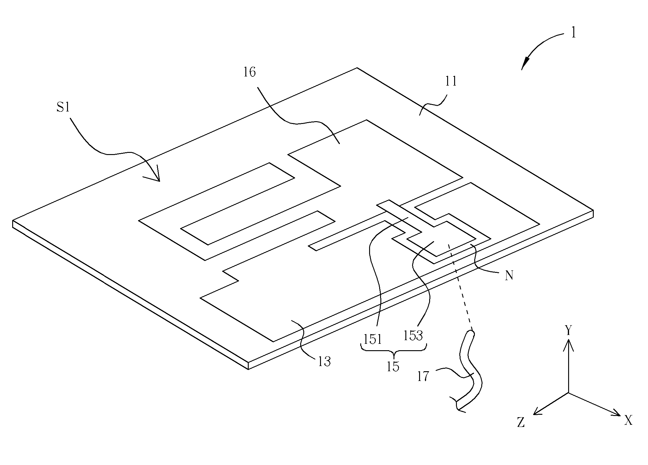
[0017]FIG. 1 shows an embodiment of the antenna 10 according to the invention. The antenna 10 includes a ground element 12, an interconnecting element 14, and a radiating element 16. Each component can be formed by an electrically conductive surface, for example, by a conductive layer in a printed circuit board. As shown in FIG. 1, the ground element 12 is used to connect with the ground, and the radiating element 16 and the ground element 12 are separated but mutually connected by the interconnecting element 14 disposed between. The radiating element 16 is divided into two radiating traces in which a crosshatched region is a first radiating trace L1, and a single-hatched region is a second radiating trace L2. The two radiating traces L1 and L2 use the interconnecting element 14 to connect with the ground element 12. In this embodiment, the interconnecting element 14 has two bent segments, so the signal can input to and output from the antenna 10 by one feeding point S of signals. I...


PUM


Abstract

An antenna includes a substrate, a ground element, a radiating element and a feed element. The ground element is disposed on the substrate and has an opening. The radiating element is disposed on the substrate and electrically connects to the ground element. The radiating element comprises a first radiating trace and a second radiating trace. The first radiating trace includes a first segment, a second segment, and a first bended portion connected the first segment and the second segment. The second radiating trace connects to the second segment of the first radiating trace. The feed element is disposed on the substrate and electrically connects to the radiating element. The feed element and the radiating element are at the same surface of the substrate, and a part of the feed element extends and enters the opening.

Description

CROSS REFERENCE TO RELATED APPLICATIONS [0001] This application is a Continuation-In-Part of U.S. patent application Ser. No. 11 / 164,364 entitled “Antenna Structure,” filed Nov. 21, 2005, the contents of which are incorporated by reference herein.BACKGROUND OF THE INVENTION [0002] 1. Field of the Invention [0003] The invention provides an antenna, and more specifically, a multi-frequency antenna. [0004] 2. Description of the Prior Art [0005] In the prior art, an inverted F antenna is usually used to realize a radio signal switch. As those skilled in the art know, the basic inverted F antenna includes a radiating element. One end of the radiating element connects with a ground element, and the middle of the radiating element is used as the feeding point of the signal. The ground element and the signal feeding point form two transverse portions of an F shape (The radiating element becomes the back of the F shape.). The length of the antenna has a relationship with a radiating frequenc...

Claims


Application Information

Patent Timeline
IPC IPC(8): H01Q1/24
CPCH01Q5/371H01Q9/42A61P3/04
Inventor TSAI, FENG-CHI EDDIELI, CHIA-TIEN
Owner WISTRON NEWEB
Why Eureka
Try Eureka