Light-emitting module and light-emitting unit

Inactive Publication Date: 2007-02-08
ROHM CO LTD
View PDF2 Cites 83 Cited by
  • Summary
  • Abstract
  • Description
  • Claims
  • Application Information

AI Technical Summary

Benefits of technology

[0006] In order to overcome the problems described above, preferred embodiments of the present invention provide a light-emitting module including multiple light-emitting devices, such as LED chips, that prohibits or reduces the

Problems solved by technology

However, in the configuration in which multiple LED chips are aligned two-dimensionally for obtaining a desired light intensity, it is not practically possible to use the light-emitting module as a point light source.
That is, it was not possible to use such a light-emitting module containing multiple LED chips as a point light source having a relatively high light intensity, which unfavorably resulted in the restriction of the use of LED chips as a li

Method used


Image

  • Light-emitting module and light-emitting unit
  • Light-emitting module and light-emitting unit
  • Light-emitting module and light-emitting unit

Examples


Example

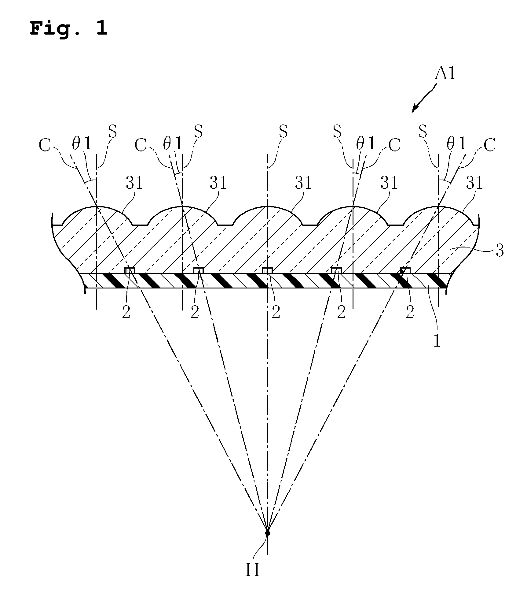
[0031] Hereinafter, preferred embodiments of the present invention will be described specifically with reference to the drawings. For convenience in description, the vertical direction will be determined with reference to FIG. 1.

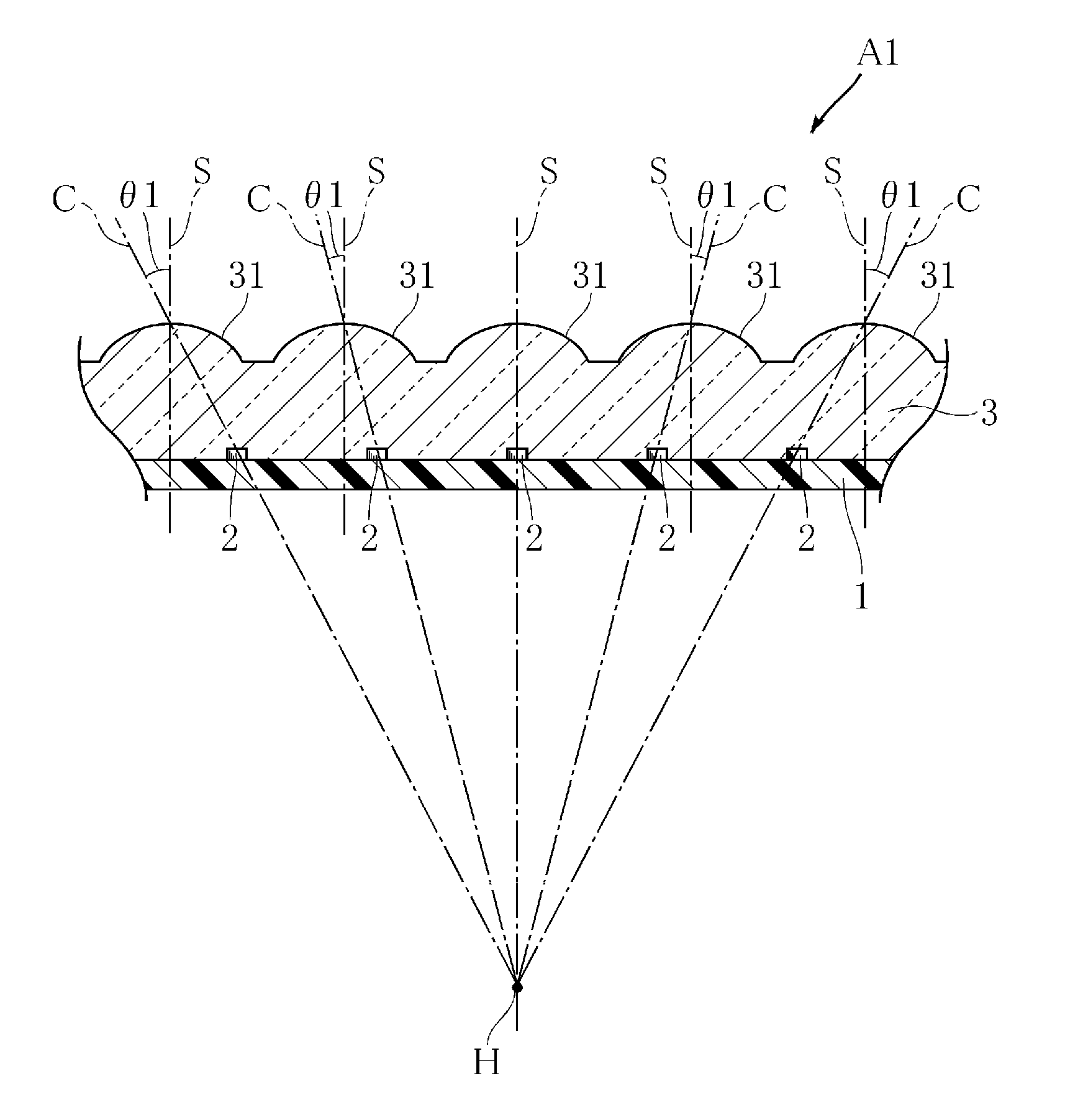
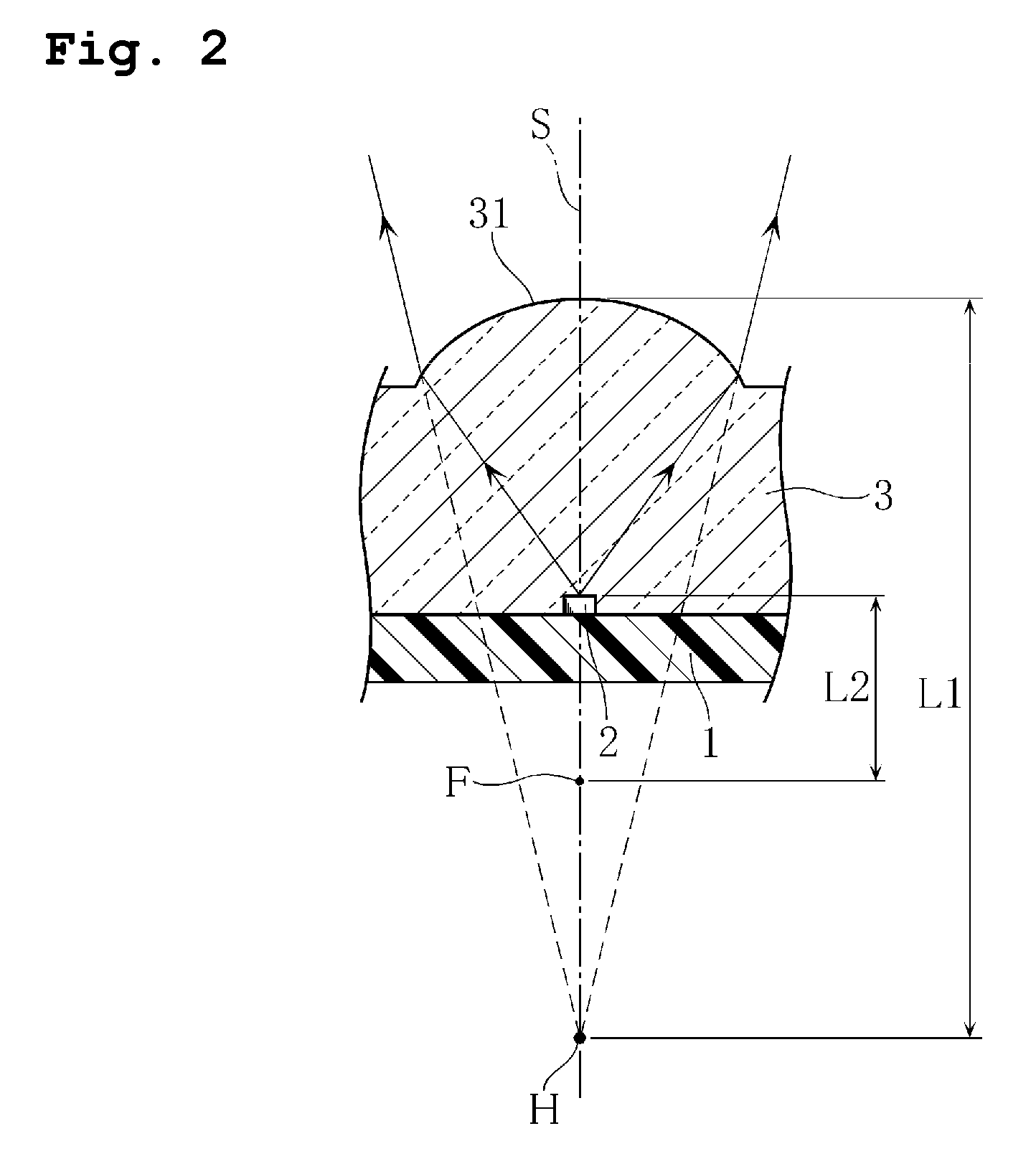
[0032] FIGS. 1 to 3 are views illustrating the light-emitting module in a preferred embodiment of the present invention. The light-emitting module A1 in the present preferred embodiment has a configuration including a substrate 1, multiple light-emitting devices 2, and a resin or plastic package 3, which is favorable for use as a light source for various lighting fixtures.

[0033] The substrate 1 is preferably, for example, made of a glass epoxy resin and has a flat plate-shape. A common wiring (not shown in FIG. 1) is provided on the surface of the substrate 1. The common wiring is connected to a pair of electrodes of each light-emitting device 2 and also to a terminal for external connection (not shown in FIG. 1). Multiple light-emitting devices 2 are bond...


PUM


Abstract

A light-emitting module includes a substrate, multiple light-emitting devices arranged thereon, and a package enclosing the multiple light-emitting devices. The package has multiple optical devices corresponding to the multiple light-emitting devices that converge and emit rays of light emitted from each of the light-emitting devices. When the outgoing rays of light emitted from the light-emitting device is extended toward the substrate, the package has virtual light-emitting regions spaced farther from the optical devices than the respective light-emitting devices, and the virtual light-emitting regions are located almost at the same position.

Description

BACKGROUND OF THE INVENTION [0001] 1. Field of the Invention [0002] The present invention relates to a light-emitting module including light-emitting devices such as LED chips, and in particular, to a light-emitting module for use as a light source for various lighting fixtures. [0003] 2. Description of the Related Art [0004] Recently, light-emitting modules containing multiple LED chips are used more commonly, replacing conventional incandescent lamps as a light source for indoor lighting fixtures, signals, and other devices. Such a light-emitting module containing multiple LED chips is described, for example, in Japanese Unexamined Patent Publication No. 11-17228 (Patent Document 1). The light-emitting module described in Patent Document 1 has a structure in which multiple light-emitting diodes (light-emitting units), in which the LED chips are sealed, for example, with a transparent resin, are aligned two-dimensionally. In the light-emitting module having such a configuration, th...

Claims


Application Information

Patent Timeline
IPC IPC(8): F21V5/00H01L33/50H01L33/54H01L33/56H01L33/62
CPCF21K9/00H01L25/0753H01L33/54H05K1/0284F21V19/0025F21Y2101/02H01L2224/45144H01L24/45H01L2224/48247H01L2924/00H01L2924/12041H01L2924/1815F21Y2115/10H01L2924/181
Inventor ICHIHARA, JUN
Owner ROHM CO LTD
Why Eureka
Try Eureka