Node apparatus, optical wavelength division multiplexing network, and system switching method

a technology of optical wavelength division and node apparatus, applied in loop networks, multiplex communication, instruments, etc., can solve the problems of drawbacks of expenditure efficiency and considerable initial expenditure, and achieve the effect of reducing initial expenditure and simplifying the constitution

Inactive Publication Date: 2007-02-08
NIPPON TELEGRAPH & TELEPHONE CORP
View PDF17 Cites 12 Cited by
  • Summary
  • Abstract
  • Description
  • Claims
  • Application Information

AI Technical Summary

Benefits of technology

[0009] Accordingly, it is an object of this invention to provide an optical wavelength division multiplexing network which can carry out large-capacity optical access services with a simpler constitution. It is a more specific object of this invention to provide the optical wavelength division multiplexing network which enables initial expenditure to be reduced in large-capacity optical access services using ONU.
[0032] In this invention, the center node belonging to the highest level network and the ONU establish a direct communication path by using lights of different wavelengths. At the nodes therebetween, the signals are amplified, branched, and routed in their optical format without being electrically processed. In other words, the center node of the network which is the final multiplexing destination of the traffic can be directly linked to the user by an optical signal at a certain wavelength. No electrical processing is performed at the nodes in between. The users and the center node are directly joined by optical signals at different wavelengths. In this case, only the center node multiplexes traffic from users, and carries out electrical processing such as communicating with other users in the regional network, distributing traffic to the core network, and the like. Therefore, according to this invention, it is possible to provide an optical wavelength division multiplexing network which can carry out large-capacity access services with a simpler constitution.

Problems solved by technology

Consequently, the initial expenditure is considerable.
Moreover, depending on the region, there may be fewer users per node, leading to a drawback of expenditure efficiency.

Method used


Image

  • Node apparatus, optical wavelength division multiplexing network, and system switching method
  • Node apparatus, optical wavelength division multiplexing network, and system switching method
  • Node apparatus, optical wavelength division multiplexing network, and system switching method

Examples


embodiment 1

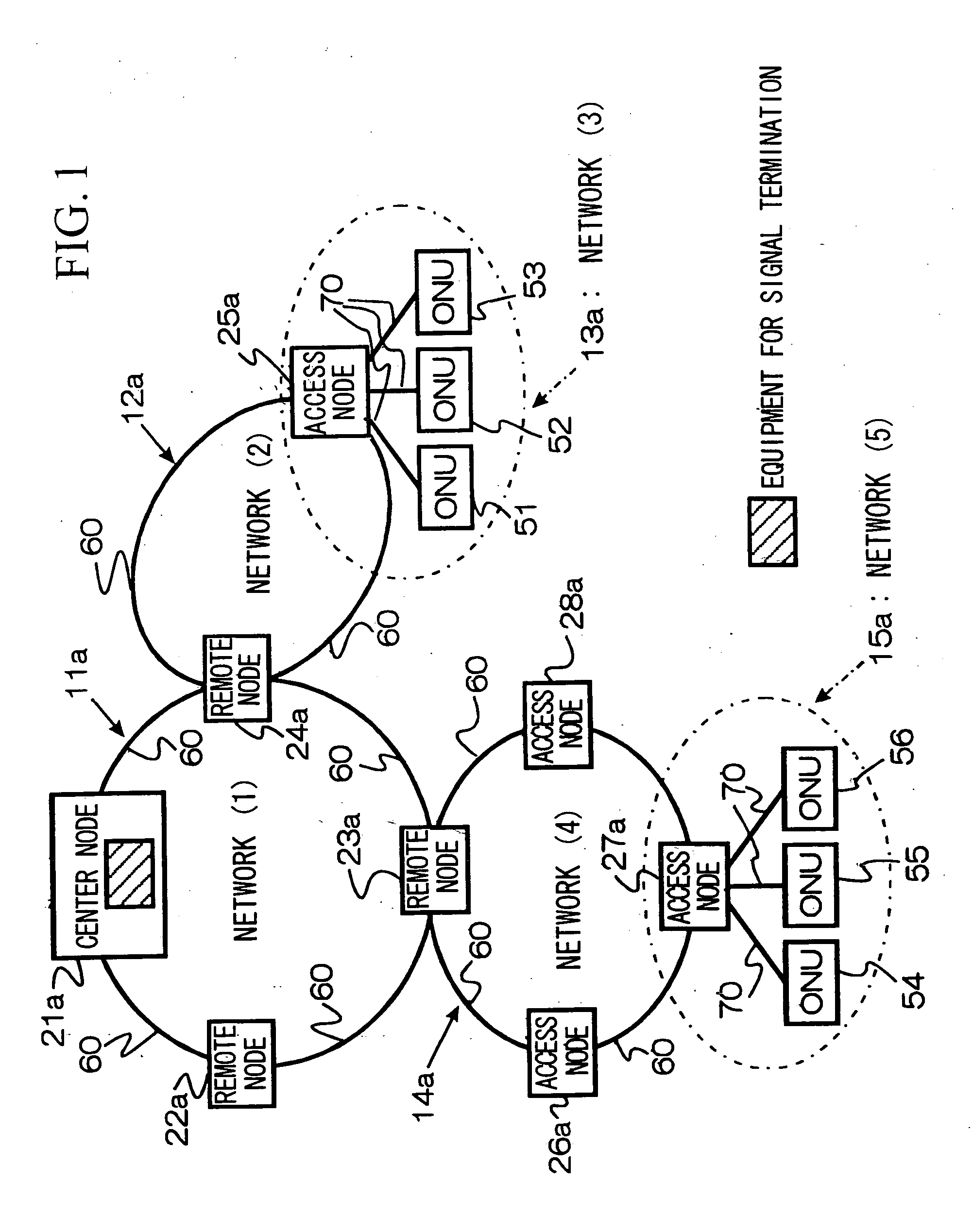
[0063]FIG. 1 is a block diagram showing the entire constitution of the optical wavelength division multiplexing network in this embodiment and in embodiments subsequently explained. As shown in FIG. 1, parts of the constitution which are identical to those in FIG. 25 are represented by the same reference numerals. Parts of the constitution which correspond to those in FIG. 25 are specified by adding the letter “a” to the end of the reference numerals shown in FIG. 25.

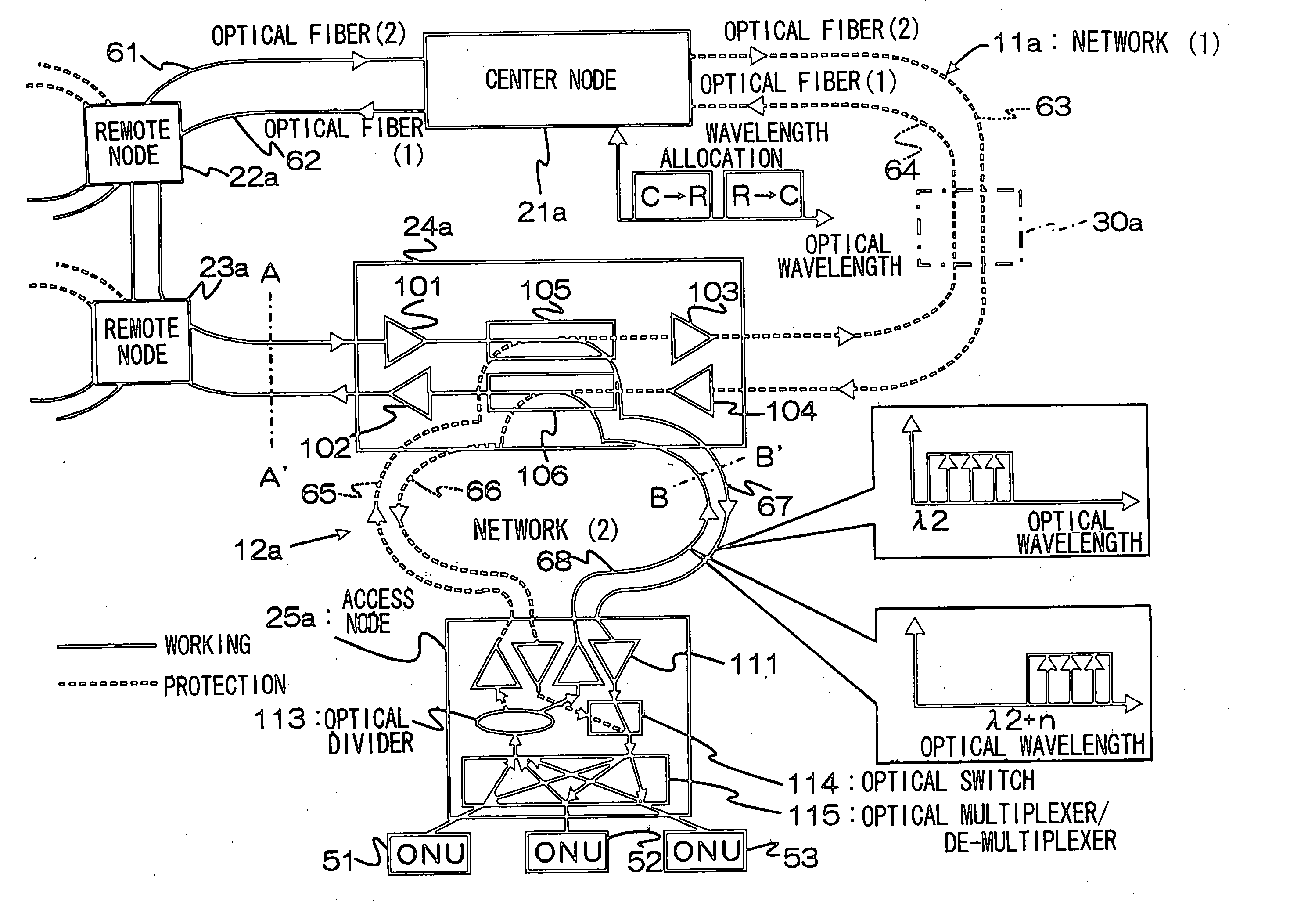
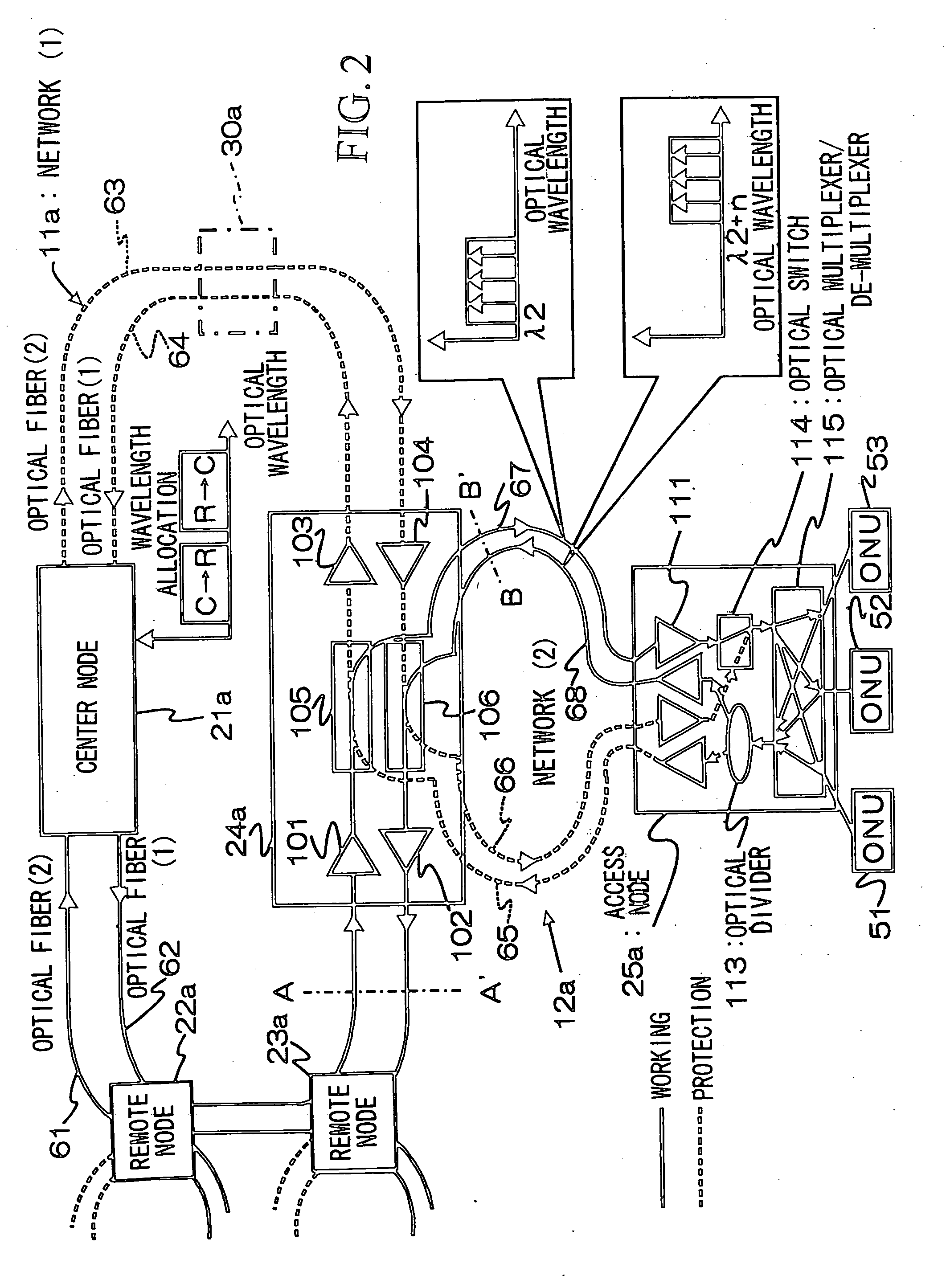
[0064] The first embodiment will be explained with reference to FIGS. 1 and 2. FIG. 2 is a block diagram showing the constitutions of the network (1) 11a, the network (2) 12a, and the network (3) 13a, shown in FIG. 1. This embodiment uses a two-fiber bi-directional ring constitution, in which the nodes of the networks (1) 11a, (2) 12a, etc., are connected by pairs of optical fibers which transmit optical signals in differing directions. For example, in the network (1) 11a, the nodes are connected by optical fibers (1) ...

embodiment 2

[0080]FIG. 3 shows an embodiment comprising a double ring. This embodiment differs from that shown in FIG. 2 in that (i) a plurality of access nodes are connected to the remote node, (ii) the access nodes are connected in a ring, and particularly (iii) this embodiment comprises an optical band pass filter which prevents optical signals at the wavelengths allocated to the ONU 54, 55, and 56, which belong to the ring network (4) 14a comprising the remote node 23a, from passing around the ring network. An optical band pass filter 301 which passes only wavelengths allocated for transmission from the remote node 23a to the center node 21a, and optical band pass filter 302 which passes only wavelengths allocated for transmission from the center node 21a to the remote node 23a, are connected to the input and output terminals of the optical coupler 105 in the remote node 23a. In addition, the optical band pass filters 301 and 302 are connected to the input and output terminals of an optical...

embodiment 3

[0083]FIG. 7 shows an embodiment comprising a two-fiber unidirectional ring. This embodiment is characterized in that the transmission direction of the optical signal from the center node 21a to the remote node 24b (corresponding to the remote node 24a of FIG. 2) is the same as the transmission direction of the optical signal from the remote node 24b to the center node 21a. FIG. 7 shows the constitution of the remote node 24b and the access node 25a at this time. This constitution differs from that shown in FIG. 2 in that the up and down signals from the access node 25a are input to identical optical couplers 105b and 106b, provided at the remote node 24b. The optical fibers 67b and 68b (corresponding to the optical fibers 67 and 68 of FIG. 2) are connected to the optical coupler 105b, and the optical fibers 65b and 66b (corresponding to the optical fibers 65 and 66 of FIG. 2) are connected to the optical coupler 106b. Here, the network (1) 11b comprising the center node 21a is arra...


PUM


Abstract

An optical wavelength division multiplexing network has a multi-level structure where a plurality of optical network units (ONUs) are connected to a lowest-level network. A node apparatus connected to networks other than the lowest-level network includes (a) passive optical components to branch optical signals from a higher-level network to a lower-level network, and couple optical signals from the lower-level network to the higher-level network, and (b) optical amplifiers for the optical signals. A node apparatus connected to the lowest-level network includes (a) an optical multiplexer / de-multiplexer to de-multiplex optical signals from the higher-level network, selectively output an optical signal to each ONU, and multiplex wave-length specific optical signals from the ONUs into a multiplexed optical signal, and (b) optical amplifiers for the optical signals. The node apparatuses provide an optical communication path between the higher-level network and the lower-level (or lowest-level) network without converting the optical signals into electrical signals.

Description

STATEMENT OF RELATED APPLICATION [0001] The present application is a divisional application of U.S. patent application Ser. No. 09 / 785,402, filed Feb. 20, 2001 (now allowed), in the name of the same inventors, which in turn claims the benefit of priority based on Japanese Patent Application Nos. 2000-043293, filed Feb. 21, 2000, and 2000-240232, filed Aug. 8, 2000, all commonly owned herewith.BACKGROUND OF THE INVENTION [0002] 1. Field of the Invention [0003] The present invention relates to an optical wavelength division multiplexing network which multiplexes and transmits optical signals having a plurality of different wavelengths. [0004] 2. Description of the Related Art [0005]FIG. 25 shows an example of the constitution of a conventional optical wavelength division multiplexing network. The network shown in FIG. 25 has a ring structure comprising two or three layers. The network of FIG. 25 will be explained in separate sections comprising a network (1) 11, a network (2) 12, a ne...

Claims


Application Information

Patent Timeline
Patent Type & Authority Applications(United States)
IPC IPC(8): H04B10/00H04B10/03H04B10/032H04B10/079H04B10/27H04B10/272H04B10/275H04B10/297H04J14/00H04J14/02H04L12/42H04Q3/52H04Q11/00
CPCH04B10/271H04B10/272H04B10/2755H04J14/02H04J14/0282H04Q2011/0086H04J14/0286H04J14/029H04Q11/0062H04Q11/0067H04J14/0283
Inventor TAKACHIO, NOBORUIWATSUKI, KATSUMIOBARA, HITOSHI
Owner NIPPON TELEGRAPH & TELEPHONE CORP
Why Eureka
Try Eureka