Rotor for passively stable helicopter

Inactive Publication Date: 2007-02-08
FLIR UNMANNED AERIAL SYST AS
View PDF6 Cites 11 Cited by
  • Summary
  • Abstract
  • Description
  • Claims
  • Application Information

AI Technical Summary

Benefits of technology

[0017] The present invention disclosed a new rotor that has a drastically reduced number of

Problems solved by technology

The necessary means to varying and controlling the pitch angle of each blade are normally complicated, expensive and add weight to the helicopter.
Thirdly, in a rotor that moves horizontally the rotor blades will have different relative airspeed depending on where

Method used


Image

  • Rotor for passively stable helicopter
  • Rotor for passively stable helicopter
  • Rotor for passively stable helicopter

Examples


Embodiment Construction

[0034] In the following the present invention will be discussed and the preferred embodiment described by referring to the accompanying drawings. Some alternative embodiments will be described, however, people skilled in the art will realize other modifications within the scope of the invention as defined in the enclosed independent claims.

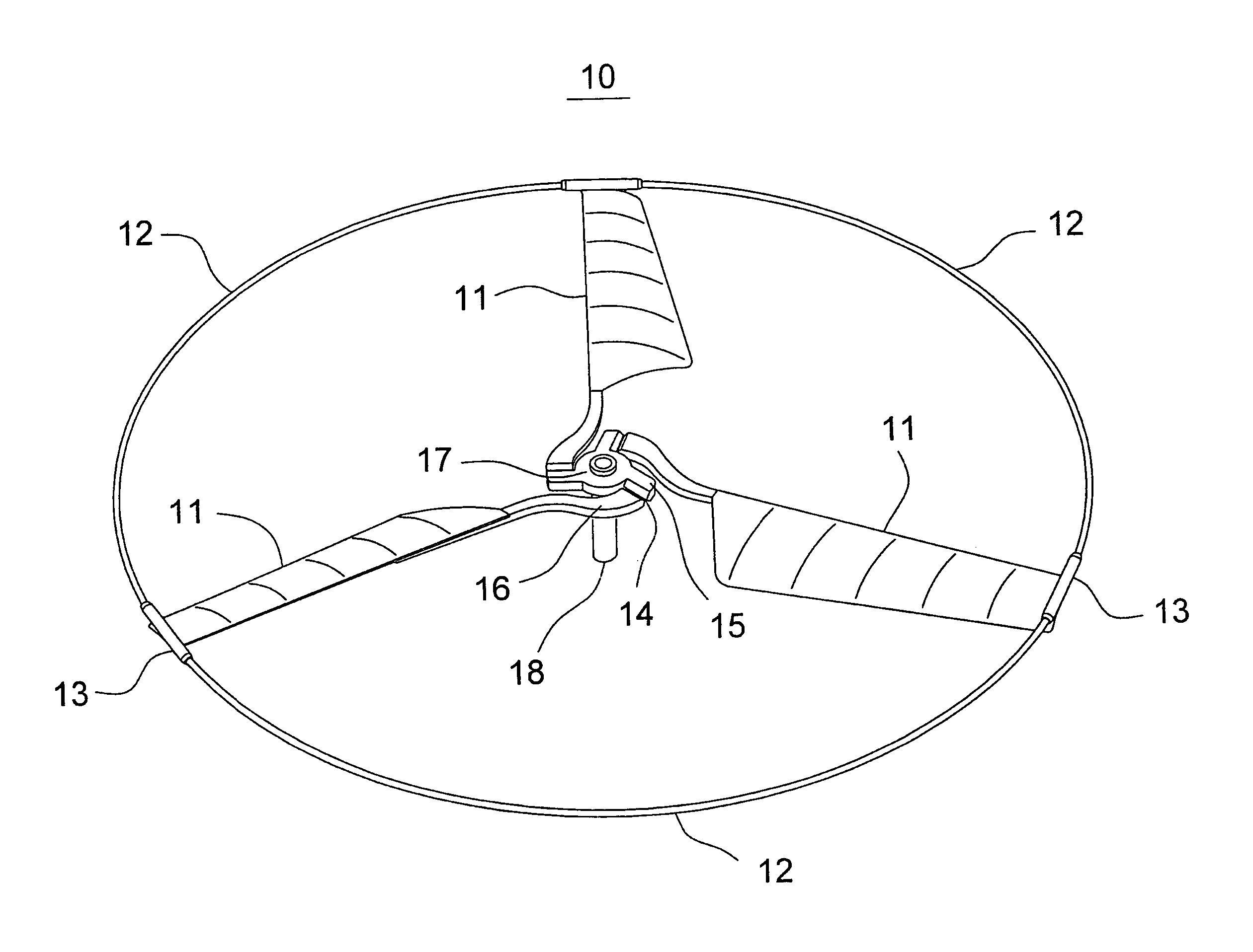
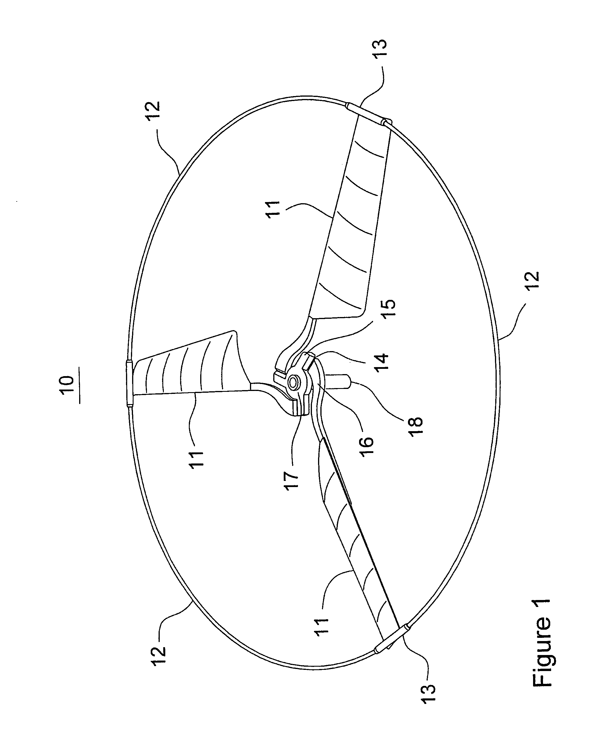
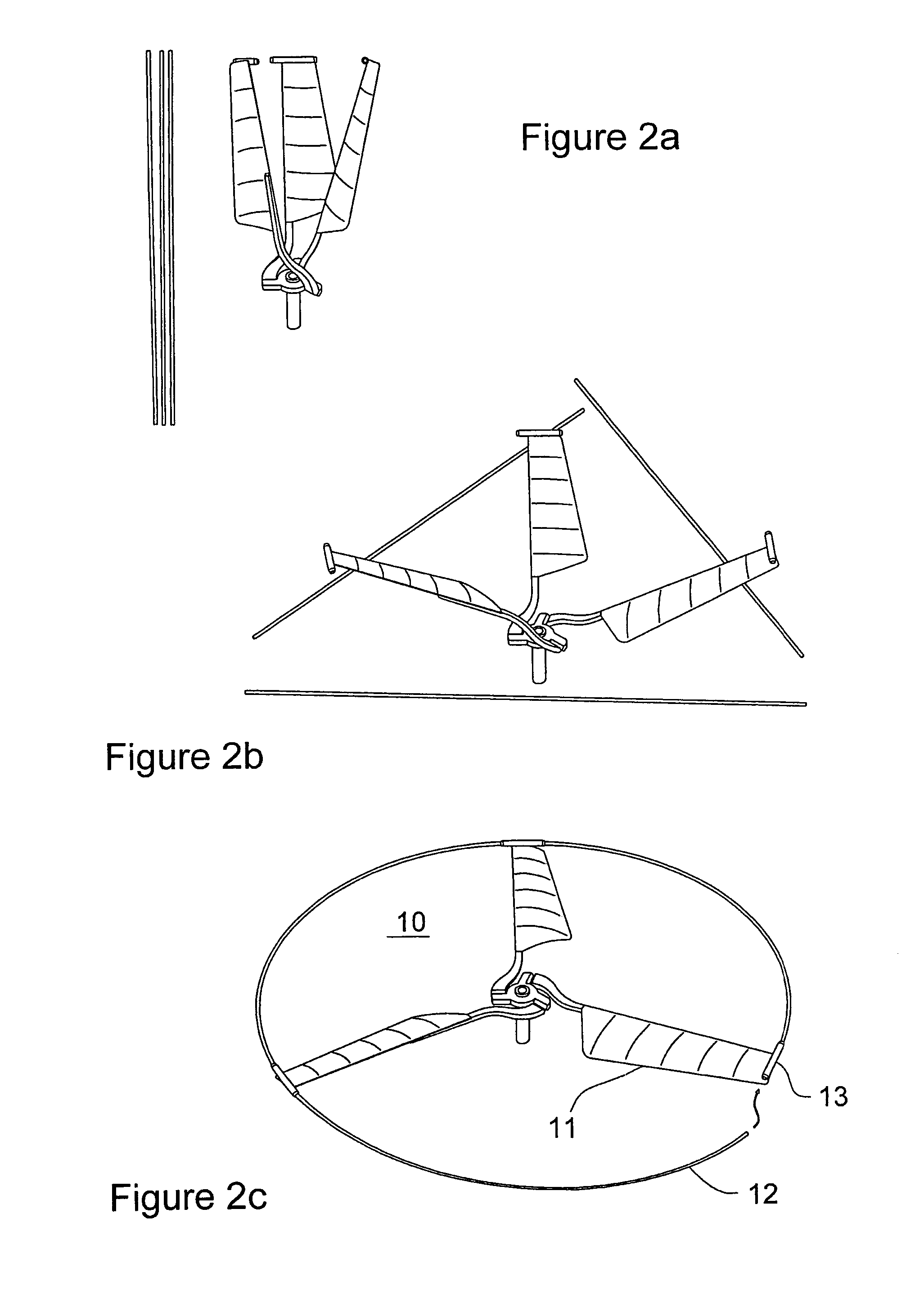
[0035] In FIGS. 1 and 2 the preferred embodiment of a rotor according to the present invention is shown. The rotor has a rotating plane defined by the path that the tip of the rotor blades follows when the rotor rotates and a fixed reference plane being perpendicular to the rotor shaft axis.

[0036] By designed a rotor system according to the principles described in US2004 / 0245376 (the entire contents of which are hereby incorporated by reference) an aircraft will be able to achieve passively stable hover. This implies that the rotating plane must be able to tilt in any direction with respect to the reference plane, furthermore the rotor blades mu...


PUM


Abstract

A rotor (10) that enables an aircraft to become passively stable in hover. The inner part of the rotor blades (11) have a pitch angle fixed relative to a reference plane perpendicular to the rotor shaft (18) axis, and the tip of the rotor blades being connected to a ring (12) encircling the rotor. Each blade is connected to the rotor shaft by a separate hinge having a hinge axis perpendicular to both the rotor shaft axis and to the blade. Because the rotor blades can also easily twist the rotor can tilt freely in any direction. The rotor blades may be disconnected from the ring and folded up for easy transport.

Description

FIELD OF THE INVENTION [0001] The present invention relates to rotary wing aircrafts such as helicopters, and in particular to a simplified mechanical solution for a rotor that enables passively stable hover. It also relates to different ways of utilizing the invention in such rotors. BACKGROUND OF THE INVENTION [0002] Typically, rotary wing aircrafts like helicopters are sustained by a rotor, rotating about a vertical rotor shaft, generating lift or upward thrust. In a conventional helicopter the thrust from the rotor can be controlled by changing the pitch angle (or in short; the pitch) of the rotor blades. The pitch is in the field of propeller aerodynamics defined as the lateral angle between the blades and a reference plane perpendicular to the rotor shaft axis. [0003] By collectively changing the pitch of all the rotor blades or by changing the rotational speed of the rotor, the helicopter can be controlled in the vertical direction. The horizontal direction of flight and the ...

Claims


Application Information

Patent Timeline
IPC IPC(8): B64C27/50
CPCA63H27/12B64C27/50B64C27/32
Inventor MUREN, PETTER
Owner FLIR UNMANNED AERIAL SYST AS
Why Eureka
Try Eureka