
Internal Breaker for Oilfield Treatments

a technology of oilfield treatment and internal breakers, which is applied in the direction of fluid removal, chemistry apparatus and processes, borehole/well accessories, etc., can solve the problems of unsatisfactory fluid loss, undesirable rate of fluid leakage into porous rock, and inability to maintain the filter cak

Inactive Publication Date: 2007-02-08
SCHLUMBERGER TECH CORP
View PDF42 Cites 79 Cited by
  • Summary
  • Abstract
  • Description
  • Claims
  • Application Information

AI Technical Summary

Benefits of technology

[0019] Yet another embodiment is a fluid composition including a viscosifier, and a solid additive involving particles sufficiently small to enter subterranean formation pores; ...

Problems solved by technology

Such applications are those in which, without a filter cake, fluid would leak off into porous rock at an undesirable rate during a well treatment.
Typically, after these treatments have been completed the continued presence of the filter cake is undesirable or unacceptable.
However, they sometimes experience undesirably high fluid loss, especially when formations with permeabilities greater than about 5 mD are treated.
This can sometimes be done in the wellbore but normally cannot be done in a proppant or gravel pack.
However, these methods require fluid flow and often result in slow or incomplete filter cake removal.
Sometimes a breaker may be incorporated in the filter cake but these must normally be delayed (for example by esterification or encapsulation) and they are often expensive and / or difficult to place and / or difficult to trigger.
However, formation of internal filter cakes is usually avoided, since in the past they have been difficult, if not impossible, to remove.
The use of a hydrolysable polyester material for use as an FLA for conventional fluid loss control has previously been proposed; further, degradation products of such materials have been shown to cause delayed breaking of fracturing fluids.
The fluid in that Patent Application also contains a pH control agent, present in an amount sufficient to neutralize any acid present in the solid hydrolysable polyacid before the injection and to neutralize any acid generated by the solid hydrolysable polyacid during the injection, so that the acid breaker is not available to break the fluid during the injection.

Method used


Image

  • Internal Breaker for Oilfield Treatments
  • Internal Breaker for Oilfield Treatments
  • Internal Breaker for Oilfield Treatments

Examples


example 1

Waxes

[0115] As with other materials suitable as IFCMB's, when wax particles are significantly smaller that the formation pore sizes, then the wax particles act only as sources of a breaker. In this case, they release a breaker for most viscoelastic surfactant based fluid systems when they melt. When the particles are larger relative to the pore throats of the formation, they form an internal filter cake, and then when they melt they provide the breaker. One skilled in the art will know how to choose the appropriate size range that will or will not form an external or internal filter cake for a given formation, and will know how to test to determine the proper wax particle concentration.

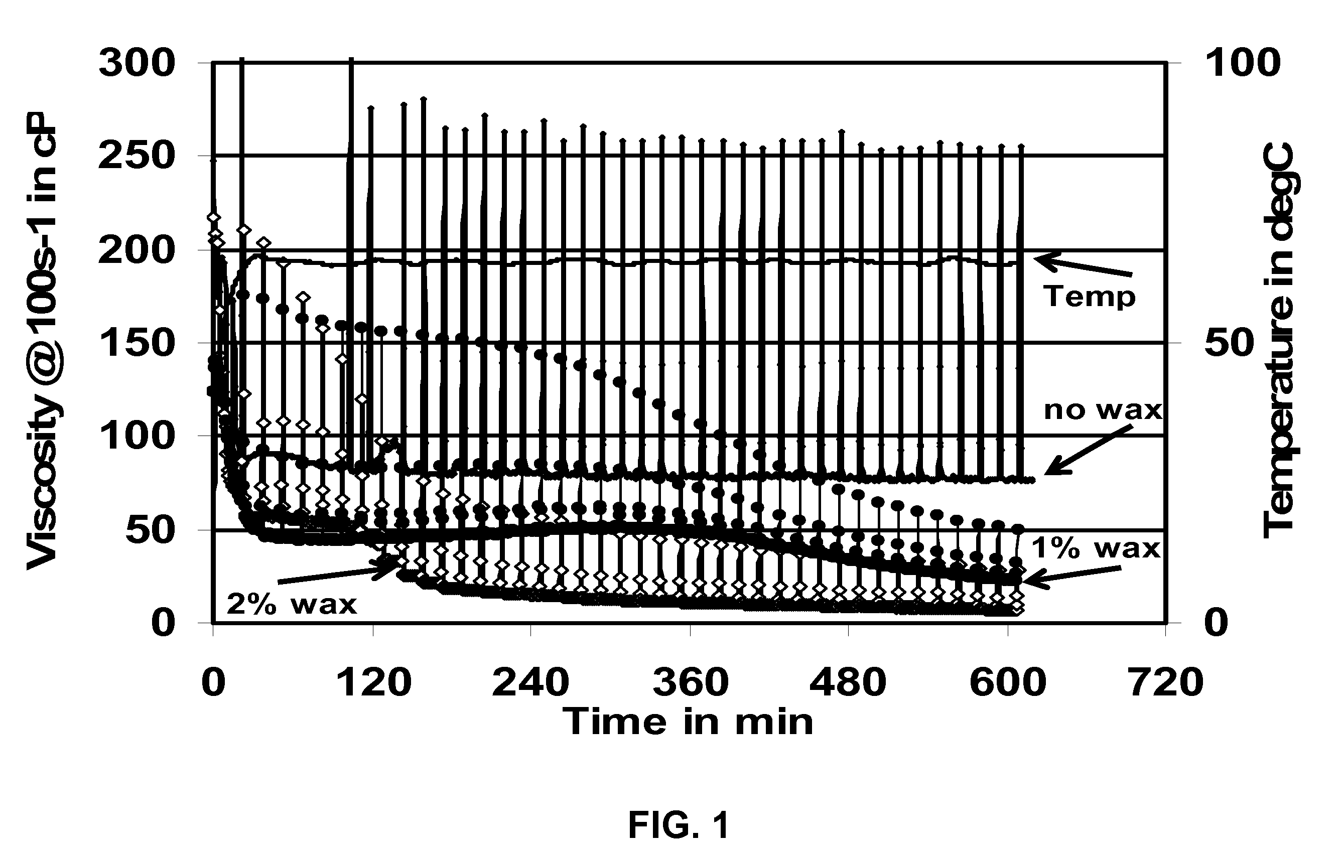
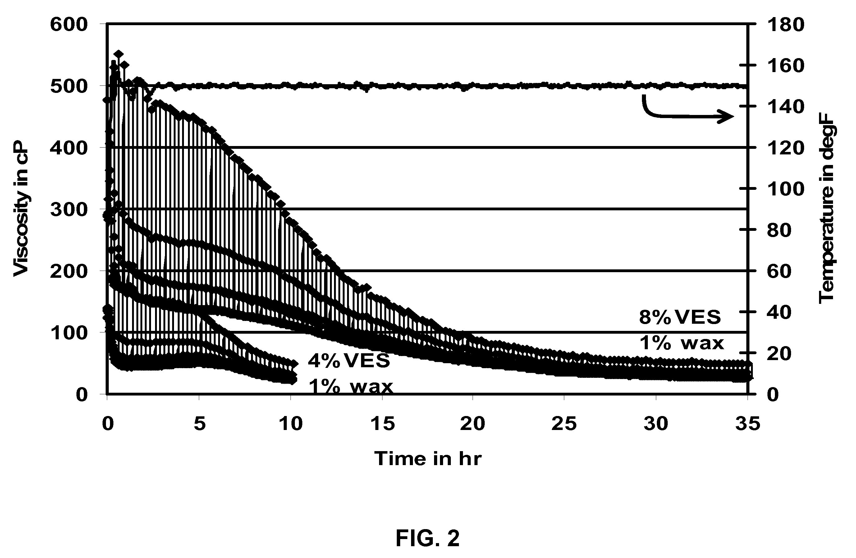
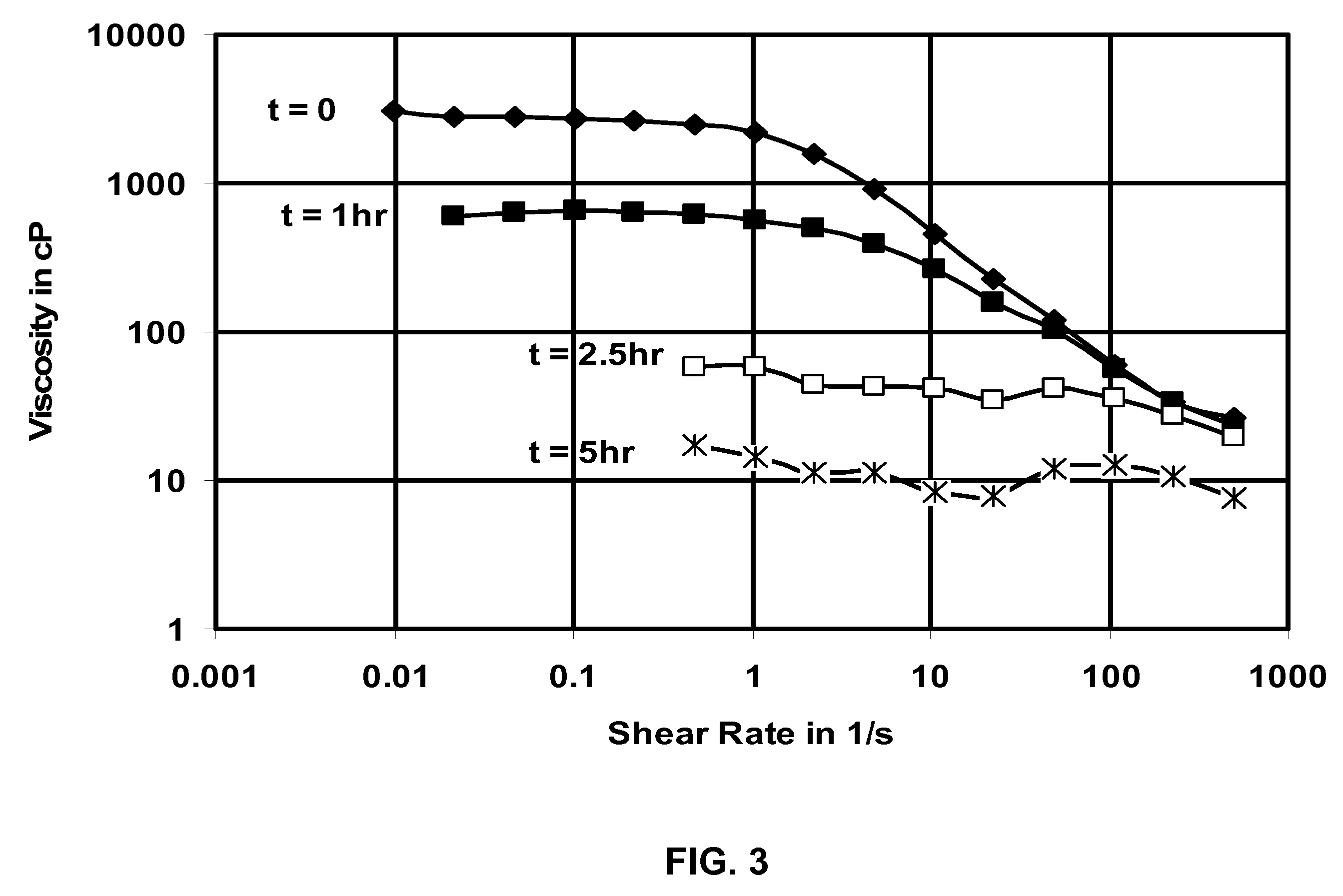
[0116]FIG. 1 shows the viscosity as a function of time at 65.6° C. (150° F.) of a fluid viscosified with 4 weight percent of a viscoelastic surfactant concentrate containing about 38 weight % erucylamidopropyl dimethyl betaine surfactant, 1.1 weight % polynaphthalene sulfonate, 22 weight % isopropa...

example 2

Polyesters

[0122] That carboxylic acids released by the degradation of polyesters are VES breakers is demonstrated in FIG. 7, which shows measurements of the viscosity of one example of a VES fluid system with different amounts of glycolic acid (GA) dissolved in the fluid. Measurements were conducted at 66° C. (150° F.). The buffer used in the experiments shown in FIG. 7 was sodium sesquicarbonate, which was used at a concentration of 30 pounds per thousand gallons (3.6 g / L) in all experiments. The VES fluid system was made with 6% of the same viscoelastic surfactant concentrate as was used in Example 1. This experiment showed the results that would be seen as polyglycolic acid (PGA) degrades, and demonstrates the breaking effect on the fluid viscosity as the PGA hydrolyzes to form glycolic acid. In addition, the data in the figure also demonstrate that the viscosity of this VES is not significantly reduced by the addition of a pH buffer to maintain the fluid pH at approximately 9....

example 3

Dry Emulsions

[0125] The dry emulsion used was obtained from Rhodia, Inc. Cranbury, N.J., U.S. A. and was made by preparing a dispersion of an oil phase in water using a hydrophilic polymer as the shell-polymer, and then drying the resulting emulsion to form a dry solid. Such dry emulsions are usually stabilized with a surfactant and / or with a hydrophilic polymeric stabilizer. Such dry emulsion materials are a very convenient method of encapsulating organic compounds that are VES breakers, by dissolving them in the oil phase before formation of the dry emulsion. The choice of oil solvent type and amount, surfactant type and concentration, hydrophilic polymer type and amount, and VES breaker type and concentration in the oil, all have an impact on the particle size of the “dried emulsion”, as well as on the extent of the break, and the delay, when the IFCMB is used to break a VES fluid system. All of these selections depend upon the required conditions for the specific oilfield appl...


PUM


Abstract

A composition and method for improving the fluid efficiency of many oilfield treatments is given. The composition is a solid additive, in a viscosified fluid, in a size range small enough that it enters formation pores; it optionally bridges there to form an internal filter cake, and then decomposes to provide a breaker for the viscosifying system for the fluid. Examples of suitable additives include waxes, polyesters, polycarbonates, polyacetals, polymelamines, polyvinyl chlorides, and polyvinyl acetates. Degradation of the additive may be accelerated or delayed.

Description

CROSS-REFERENCE TO RELATED APPLICATIONS [0001] This application is a Continuation-in-part of, and claims the benefit of, U.S. patent application Ser. No. 11 / 159,023, filed Jun. 22, 2005, which was a Continuation-in-part of, and claimed the benefit of, U.S. patent application Ser. No. 10 / 707,022, filed Nov. 14, 2003, which was a Continuation-in-part of, and claimed the benefit of, U.S. patent application Ser. No. 10 / 227,690, filed on Aug. 20, 2002, now U.S. Pat. No. 6,938,693. This application is also a Continuation-in-part of, and claims the benefit of, U.S. patent application Ser. No. 11 / 316,021, filed Dec. 21, 2005. This application is related to copending application “Internal Breaker for Oilfield Fluids,” inventors Philip Sullivan, Yiyan Chen, Belgin Baser, Carlos Abad, Mehmet Parlar, and Gregory Kubala, filed Sep. 18, 2006. This application is also related to copending application “Oxidative Internal Breaker for Viscoelastic Surfactant Fluids,” inventors Lijun Lin, Carlos Abad,...

Claims


Application Information

Patent Timeline
IPC IPC(8): C09K8/00E21B43/00
CPCC09K8/508C09K8/5751C09K8/68C09K8/76Y10S507/923C09K2208/26C09K2208/30Y10S507/922C09K2208/18
Inventor ABAD, CARLOSLEE, JESSE C.SULLIVAN, PHILIP F.NELSON, ERIKCHEN, YIYANBASER, BELGINLIN, LIJUN
Owner SCHLUMBERGER TECH CORP
Learn More