Method and system for diagnosing, collecting information and servicing a remote system

a technology for remote systems and information, applied in the field of methods and systems for diagnosing, collecting information and servicing a remote system, can solve problems such as motor vehicles or other units being signs of potential problems, and achieve the effect of reducing costs

Inactive Publication Date: 2007-02-08
RICOH KK
View PDF54 Cites 35 Cited by
  • Summary
  • Abstract
  • Description
  • Claims
  • Application Information

AI Technical Summary

Benefits of technology

[0009] A further object of the present invention is to provide a system for communicating data obtained by monitoring the device to a central information system allowing various data formats that ease the analysis of received data at the receiving side.
[0011] A further object of the present invention is to efficiently communicate the monitored information to a transmission unit.
[0013] The present invention achieves these and other objects by monitoring the states and events of the device. The data obtained by monitoring the states and events of a device, as a further feature in the present invention, is collected, logged, and communicated to a central information system (e.g., using Internet e-mail or the File Transfer Protocol (FTP)). The use of e-mail communication reduces the costs associated with communicating such data. The data can be communicated to the central information system at several instances. Such instances include each time a user turns off the device, or after a predetermined number of times that a user has utilized and turned off the device, or after a predetermined time period, or when potential breakdown conditions exist in the device. If the configuration allows and if necessary, the direct connection such as FTP between the monitored application and the monitoring system can be established in addition to the e-mail communication.

Problems solved by technology

Some state changes in a motor vehicle or other unit may be signs of potential problems.

Method used


Image

  • Method and system for diagnosing, collecting information and servicing a remote system
  • Method and system for diagnosing, collecting information and servicing a remote system
  • Method and system for diagnosing, collecting information and servicing a remote system

Examples


Embodiment Construction

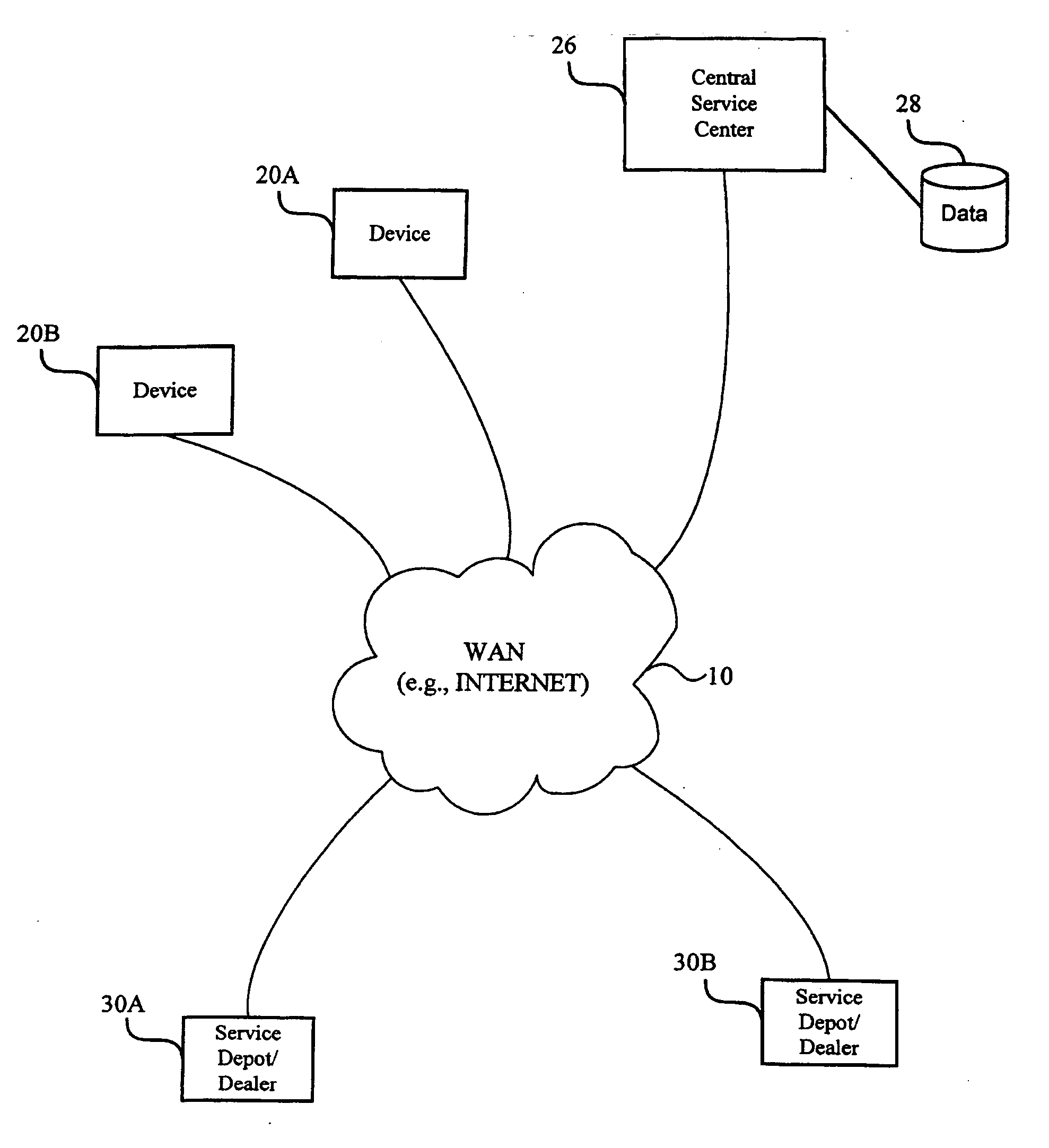
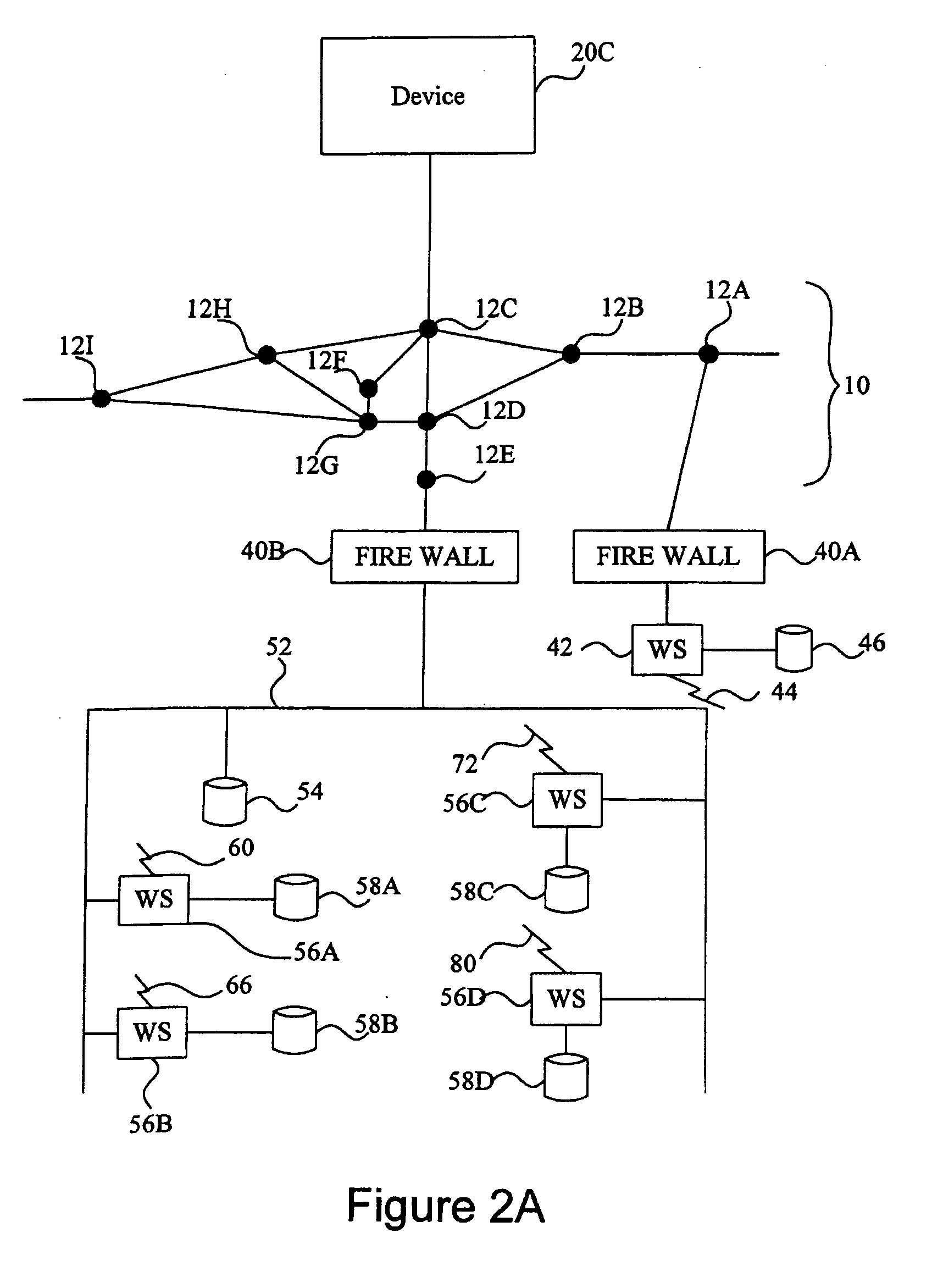
[0027] Referring now to the drawings, wherein like reference numerals designate identical or corresponding parts throughout the several views. FIG. 1 illustrates Device 20A and Device 20B whose states and events are being monitored. The devices can refer to business office machines such as copiers, facsimile machines, facsimile servers, scanners, a thin server or printers. The devices can also refer to appliances such as microwave ovens, VCRs, digital cameras, cellular phones, or palm top computers. Further, the devices can refer to metering systems (e.g., gas, water, or electricity metering systems), vending machines, or any other mechanical devices including mobile units such as automobiles, motor cycles, boats, trains and airplanes. In addition to devices referring to special purpose machines, the devices can refer to general-purpose computers.

[0028] Referring to FIG. 1, the events of Device 20A are monitored as the events occur (e.g., when the user interacts with the operation ...


PUM


Abstract

A monitoring system, method, and computer-program product tracks events and device states in a device and sends those events and states to a remote central service center using an Internet access module. The remote central service center monitors the received events and states for errors or warnings. The monitoring software (e.g., a dynamic link library) supports multiple data formats and multiple protocols to more effectively communicate the event and state information.

Description

CROSS REFERENCE TO RELATED APPLICATIONS [0001] The present application is a continuation-in-part of U.S. patent application Ser. No. 09 / 192,583, filed Nov. 17, 1998. The present application is also a continuation of U.S. patent application Ser. No. 09 / 575,710, filed Jul. 25, 2000, which is incorporated herein by reference. Moreover, the present application is related to the following U.S. applications and patents: Ser. No. 09 / 453,934, filed May 17, 2000; Ser. No. 09 / 453,935, filed May 17, 2000; Ser. No. 09 / 453,937, filed May 17, 2000; Ser. No. 09 / 440,692, filed Nov. 16, 1999; Ser. No. 09 / 440,646, filed Nov. 16, 1999; Ser. No. 09 / 440,645, filed Nov. 16, 1999; Ser. No. 09 / 393,677, filed Sep. 10, 1999; Ser. No. 09 / 311,148, filed May 13, 1999; Ser. No. 09 / 192,583, filed Nov. 17, 1998; Ser. No. 08 / 883,492, filed Jun. 26, 1997; Ser. No. 09 / 108,705, filed Jul. 1, 1998; Ser. No. 09 / 457,669, filed Dec. 9, 1999; Ser. No. 07 / 549,278, filed Jul. 6, 1990; Ser. No. 08 / 916,009, now abandoned; Ser....

Claims


Application Information

Patent Timeline
Patent Type & Authority Applications(United States)
IPC IPC(8): G06F15/16
CPCG06Q30/02H04L67/125H04L43/0817
Inventor MOTOYAMA, TETSUROFONG, AVERY
Owner RICOH KK
Why Eureka
Try Eureka