Electromagnetic Surveying for Resistive or Conductive Bodies

a technology of electromagnetic surveying and resistive bodies, applied in the field of seafloor electromagnetic surveying for resistive and/or conductive bodies, can solve the problem that the vertical field measurement is more susceptible to nois

Active Publication Date: 2007-12-13
PGS GEOPHYSICAL AS
View PDF6 Cites 34 Cited by
  • Summary
  • Abstract
  • Description
  • Claims
  • Application Information

AI Technical Summary

Benefits of technology

[0030] This can be beneficial since the comparison of the combined response data with background data can help to determine whether features of the combined response data are indicative of a resistive or conductive body or arise as a result of some other local background structure configuration. ...

Problems solved by technology

This is beneficial because vertical field measurements can be more suscepti...

Method used


Image

  • Electromagnetic Surveying for Resistive or Conductive Bodies
  • Electromagnetic Surveying for Resistive or Conductive Bodies
  • Electromagnetic Surveying for Resistive or Conductive Bodies

Examples


first embodiment

[0093] Equation 7, shown in FIG. 5G, defines a linear combination of a vertical gradient in the radial electric field data Er and the azimuthal magnetic field data Bφ used in a method of analysing results according to the invention. Combinations of the electric and magnetic field data such as this are referred to as combined response data.

second embodiment

[0094] Equation 8, shown in FIG. 5H, defines another linear combination of the vertical gradient in the azimuthal electric field data Eφ and the radial magnetic field data Br used in a method of analysing results according to the invention.

[0095] One way of obtaining the vertical gradients in the electric field data is by sampling the electric field at two (or more) different heights during surveying, for example by deploying multiple receivers at different heights or a single receiver having multiple detectors at different heights.

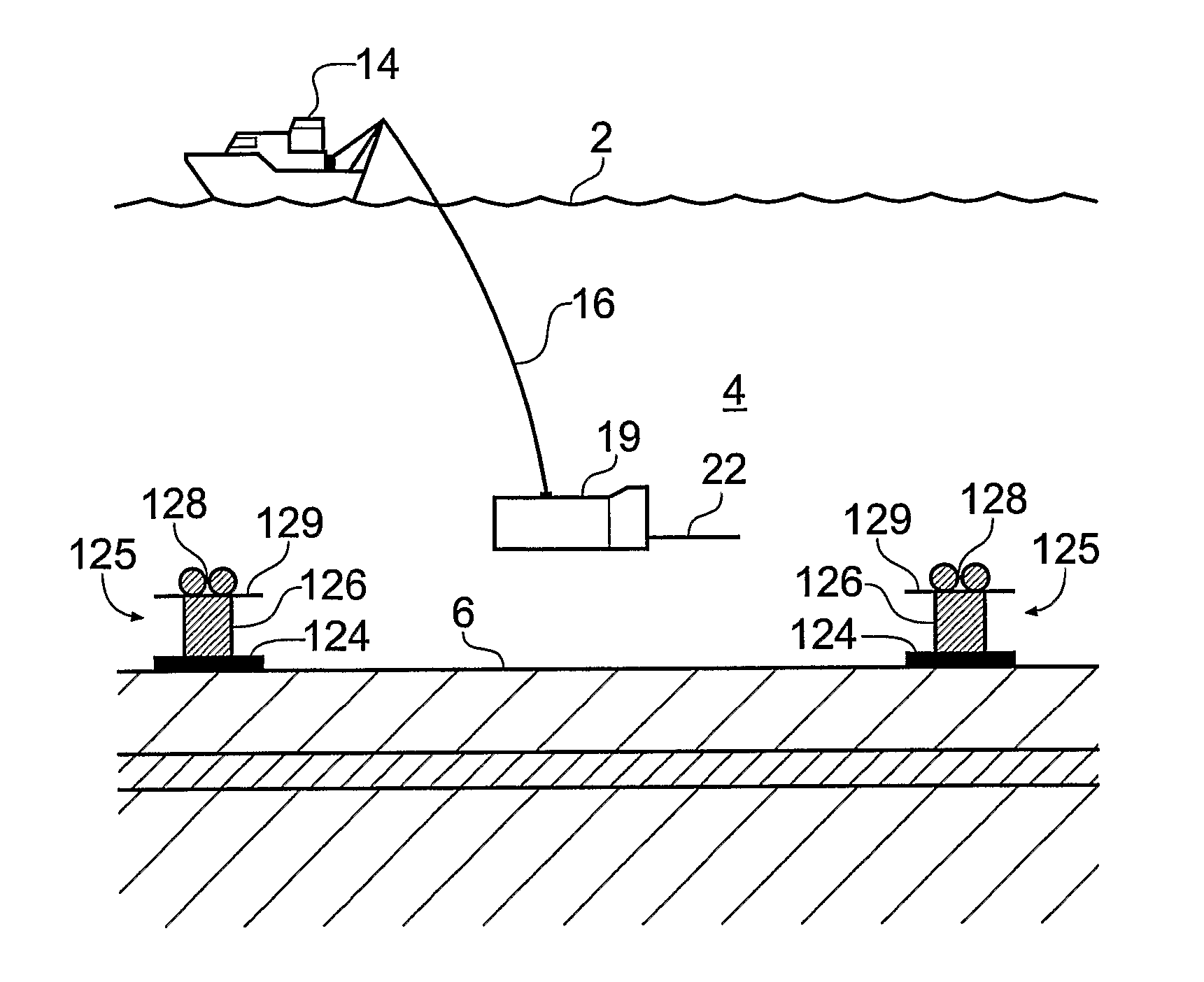
[0096]FIG. 6A schematically shows a surface vessel 14 undertaking controlled source electromagnetic (CSEM) surveying of a subterranean strata configuration using a survey method according to one embodiment of the invention. The surface vessel 14 floats on the surface 2 of a body of water, in this case seawater 4 of depth h metres. A submersible vehicle 19 carrying a source in the form of an HED transmitter 22 is attached to the surface vessel 14 by an um...


PUM


Abstract

A method of analysing electromagnetic survey data from an area of seafloor (6) that is thought or known to contain a conductive or resistive body, such as a subterranean hydrocarbon reservoir (12), is described. The method includes providing electric field data and magnetic field data, for example magnetic flux density, obtained by at least one receiver (25) from a horizontal electric dipole (HED) transmitter (22) and determining a vertical gradient in the electric field data. The vertical gradient in the electric field data and the magnetic field data are then combined to generate combined response data. The combined response data is compared with background data specific to the area being surveyed to obtain difference data sensitive to the presence of a subterranean hydrocarbon reservoir. Because the combined response data are relatively insensitive to the transverse electric (TE) mode component of the transmitted signal, the method allows hydrocarbon reservoirs to be detected in shallow water where the TE mode component interacting with the air would otherwise dominate. Furthermore, because there is no mixing between the TE and transverse magnetic (TM) modes in the combined response data, data from all possible transmitter and receiver orientations may be used. The background data may be provided by magneto-telluric surveying, controlled source electromagnetic surveying or from direct geophysical measurement.

Description

BACKGROUND OF THE INVENTION [0001] The invention relates to seafloor electromagnetic surveying for resistive and / or conductive bodies, for example for oil and other hydrocarbon reserves or subterranean salt bodies. [0002]FIG. 1 schematically shows a surface vessel 14 undertaking controlled source electromagnetic (CSEM) surveying of a subterranean strata configuration using standard techniques [1]. The subterranean strata configuration in this example includes an overburden layer 8, an underburden layer 9 and a hydrocarbon reservoir 12. The surface vessel 14 floats on the surface 2 of a body of water, in this case seawater 4 of depth h metres. A submersible vehicle 19 carrying a source in the form of a horizontal electric dipole HED transmitter 22 is attached to the surface vessel 14 by an umbilical cable 16. This provides an electrical and mechanical connection between the submersible vehicle 19 and the surface vessel 14. The HED transmitter is supplied with a drive current so that ...

Claims


Application Information

Patent Timeline
IPC IPC(8): G06G7/48E21B47/00G01V3/12G01V3/18
CPCG01V3/12G01V3/083Y02A90/30G01V3/38G01V3/165
Inventor MACGREGOR, LUCY M.ANDREIS, DAVIDTOMPKINS, MICHAEL
Owner PGS GEOPHYSICAL AS
Why Eureka
Try Eureka