Virtual magnifying glass with on-the fly control functionalities

a virtual magnifying glass and on-the-fly control technology, applied in the direction of instruments, geometric image transformation, computing, etc., can solve the problems of inability to interact with the underlying application windows within the magnification window, increase the detail, and the simplicity and convenience of the known display screen magnifiers are less than ideal

Inactive Publication Date: 2007-02-08
MICROSOFT TECH LICENSING LLC
View PDF22 Cites 119 Cited by
  • Summary
  • Abstract
  • Description
  • Claims
  • Application Information

AI Technical Summary

Benefits of technology

[0031] In accordance with an aspect of the invention, a magnifier window is created which is effectively invisible to the calls to get a desktop image to be magnified. This enables the magnifier to operate in an intuitive manner, permitting the viewer to view what is directly beneath the magnifier, and to interact with th

Problems solved by technology

Although this doesn't typically increase the detail beyond the applicable screen resolution, it does allow users to view user interface (UI) objects and text at larger sizes.
This mode allows overlay of other open windows but does not allow interaction with underlying application windows within the magnification window.
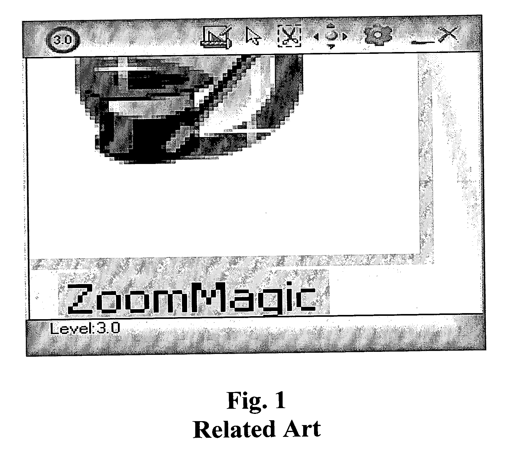
Known display screen magnifiers are less than ideal in terms of their simplicity and convenience, and the intuitiveness of their use.
Also, the manner in which some magnifiers are implemented renders them highly fragile, i.e., susceptible to malfunction in the event of operating system/driver updates and patches.
Implementing a magnification application intended for use with an operating system that provides a windows-based graphical user interface (GUI), e.g.

Method used


Image

  • Virtual magnifying glass with on-the fly control functionalities
  • Virtual magnifying glass with on-the fly control functionalities
  • Virtual magnifying glass with on-the fly control functionalities

Examples


Embodiment Construction

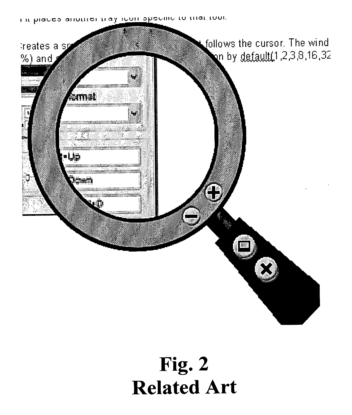
[0044] An on-screen magnifier according to the invention includes a moveable magnifier frame within which a magnified image is presented. The magnified image corresponds to screen content located within a magnification region underlying the magnifier frame, magnified to a set level of magnification.

[0045] A display screen magnifier in accordance with an embodiment of the invention is configured such that while it is activated, it remains on top of the desktop and any other open windows of a screen display. It passes events of a user input device (e.g., a mouse or keyboard) to windows located beneath the magnifier, and dynamically updates the magnified image to reflect changes in underlying screen content. Such a display screen magnifier may be embodied in software or firmware executed on a general purpose computer or other data processing device provided with a display screen and user input device.

[0046] An aspect of the invention involves achieving the above-described behavior by...


PUM


Abstract

A display screen magnifier is controllable by a user to magnify selected portions of a desktop including windows open on the screen. A moveable magnifier frame is provided, within which a magnified image is presented. The magnified image corresponds to screen content located within a magnification region underlying the magnifier frame, magnified to a set level of magnification. The magnifier is controllable through use of a user input device. At least one operational parameter of the magnifier can be adjusted, without interaction with on-screen objects and without taking focus away from the desktop or any windows open on the screen. In a particular embodiment of the invention, on-the-fly controllability of the magnifier includes its activation and deactivation, adjustment of the magnification level, and adjustment of the size of the magnifier frame.

Description

[0001] A portion of the disclosure of this patent document contains material which is subject to copyright protection. The copyright owner has no objection to the facsimile reproduction by anyone of the patent document or the patent disclosure, as it appears in the Patent and Trademark Office patent file or records, but otherwise reserves all copyright rights whatsoever. BACKGROUND OF THE INVENTION [0002] Various types of computer display screen magnification and zoom functionalities are known. In general, such magnifiers show a magnified copy of a portion of what appears on a computer's screen. Such functionalities have been provided as accessibility options for the visually impaired, and for other purposes, both as features provided within particular application software, and as specialty software intended to provide magnification / zoom functionalities generally available for use at an operating system (e.g., desktop) level and with user applications. For the visually impaired, suc...

Claims


Application Information

Patent Timeline
IPC IPC(8): G06K9/03
CPCG06F2203/04805G06F3/0481G06F9/06G06T3/40
Inventor FLEISHER, JACOBNGARI, JOSEPH K.SMITH, KEVIN J.MANN, SAMUEL A.MAIL, SCOTT MITCHELLWINSER, MICHAELESPOSITO, DAVID V.
Owner MICROSOFT TECH LICENSING LLC
Why Eureka
Try Eureka