FTTP IP video overlay

a video overlay and ip video technology, applied in the direction of optical transmission adaptation, multiplex communication, electrical equipment, etc., can solve the problem that the ip video service application requires a very small amount of resources in the ol

Inactive Publication Date: 2007-02-15
TELLABS PETALUMA
View PDF4 Cites 7 Cited by
  • Summary
  • Abstract
  • Description
  • Claims
  • Application Information

AI Technical Summary

Benefits of technology

[0015] In another embodiment of the invention, an overlay video system for a FTTP network is achieved by including a video router with a gigabit Ethernet interface including Internet Group Management Protocol (IGMP) multicasting capability in a headend. The video router transmits unidirectional IP video to a plurality of Single Family Unit (SFU) ONTs at 1550 nm. The SFU ONTs include IGMP snooping (MxU ONT with multicasting) capability and carry bi-directio...

Problems solved by technology

This approach requires very small amount of resources in the OLT for the IP video service...

Method used


Image

  • FTTP IP video overlay
  • FTTP IP video overlay
  • FTTP IP video overlay

Examples


Embodiment Construction

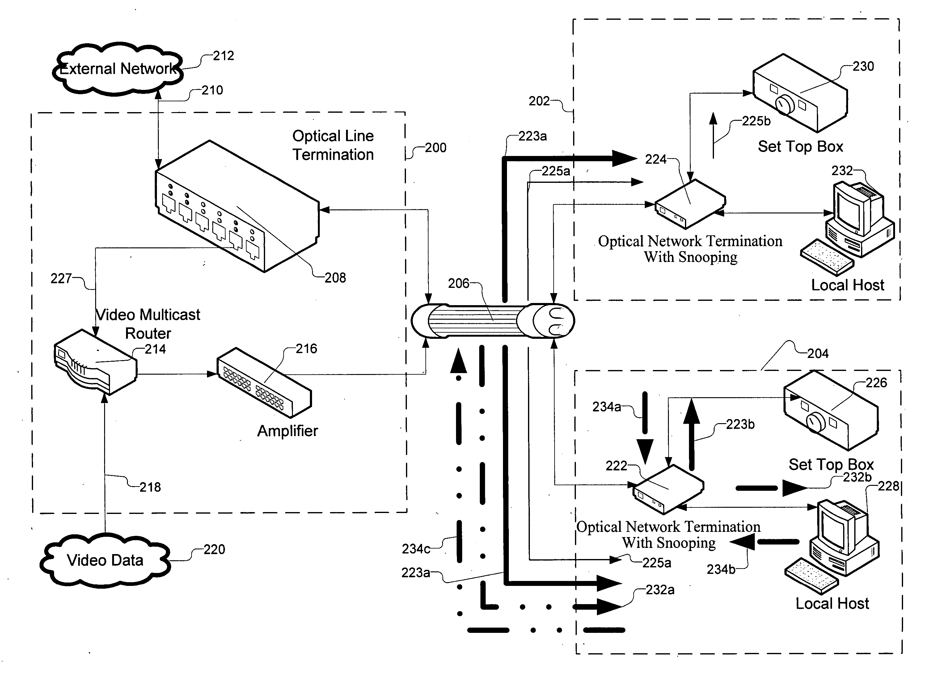
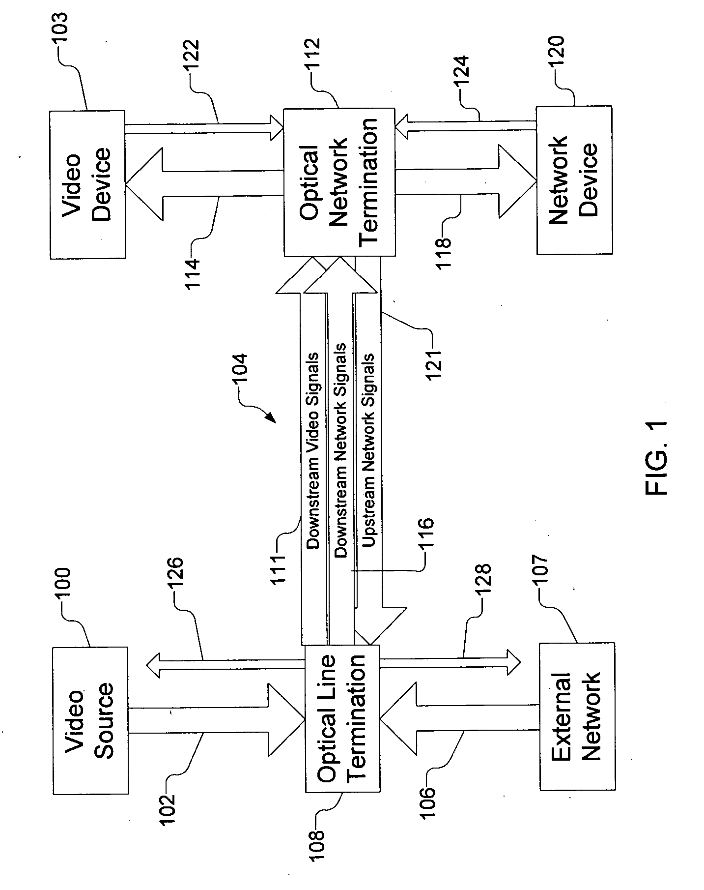
[0022]FIG. 1 is a block diagram representing an IP video overlay for a FTTP network in accordance with an exemplary embodiment of the present invention. Using an IP video overlay, downstream network video signals from a video source 100 including electrical video signals 102 intended for one or more subscribers may be routed to a video device 103 through a FTTP network 104. To do so, the downstream network video signals are combined, or overlaid, with other downstream network signals 106 from an external network 107 at a headend having an Optical Line Termination (OLT) 108. To overlay the downstream network video signals, the OLT 108 receives the electrical video signals 102 and assigns the electrical video signals 102 to a preassigned first optical wavelength utilized by the FTTP network 104. The electrical video signals 102 are converted into optical video signals in the first optical wavelength. The optical video signals are then transmitted in a downstream network video channel ...


PUM


Abstract

A video overlay system for a Fiber to the Premises (FTTP) optical network. The video overlay is achieved by including a video router with a gigabit Ethernet interface including Internet Group Management Protocol (IGMP) multicasting capability in a headend. The video router transmits unidirectional Internet Protocol video to a plurality of Single Family Unit (SFU) Optical Network Terminations (ONTs) at 1550 nm. The SFU ONTs include IGMP snooping (MxU ONT with multicasting) capability and carry bi-directional control signals from Set Top Boxes (STBs) using 1490 nm downstream and 1310 nm upstream traffic to the headend via an Optical Line Termination (OLT).

Description

BACKGROUND AND SUMMARY [0001] 1. Field of the Invention [0002] The present invention relates generally to distribution of video to subscribers on a communications network and more specifically to distributing video over an optical network. [0003] 2. Description of the Related Art [0004] There is a growing demand in the industry to find a solution to transmit video from a headend to a subscriber's premises through a fiber optic network all the way into an individual home or business. Such fiber optic networks are termed Fiber To The Home (FTTH) or Fiber To The Premises (FTTP) networks. [0005] In a FTTP network, equipment at a headend or central office couples the FTTP to external services such as a Public Switched Telephone Network (PSTN) or an external network. Signals received from these services are converted into optical signals and are combined onto a single optical fiber at a plurality of wavelengths, with each wavelength defining a channel within the FTTP network. The optical ...

Claims


Application Information

Patent Timeline
IPC IPC(8): H04J14/00
CPCH04J14/0226H04J14/0227H04J14/0282H04J14/0238H04J14/0247H04J14/0252H04N7/22
Inventor BLAKLEY, SEAN V.PATEL, PRADEEP D.CONKLIN, THOMAS E.
Owner TELLABS PETALUMA
Why Eureka
Try Eureka