Capacity modulated scroll compressor

a compressor and capacity modulation technology, applied in machines/engines, liquid fuel engines, positive displacement liquid engines, etc., can solve the problems of reducing affecting the performance of the compressor, so as to reduce the compression ratio of the compressor, facilitate the wide range of loading, and facilitate the effect of capacity modulation

Inactive Publication Date: 2007-02-15
EMERSON CLIMATE TECH INC
View PDF75 Cites 52 Cited by
  • Summary
  • Abstract
  • Description
  • Claims
  • Application Information

AI Technical Summary

Benefits of technology

[0002] Capacity modulation is often a desirable feature to incorporate into the compressors of air conditioning and refrigeration systems in order to better accommodate the wide range of loading to which the systems may be subjected. Many different approaches have been utilized for providing this capacity modulation feature. These approaches have ranged from control of the suction inlet of the compressor to bypassing compressed discharge gas back into the suction pressure zone of the compressor. With a scroll-type compressor, capacity modulation has often been accomplished by using a delayed suction approach which comprises providing ports at various positions extending through one of the base plates which, when opened, allow the initially formed compression chambers between the intermeshing scroll wraps to communicate with the suction zone of the compressor. This delays the point at which the se...

Problems solved by technology

This delays the point at which the sealed compression chambers are formed and, thus, delays the start of compression of the suction gas.
This method of capacity modulation has the effect of actually reducing the compression ratio of the compressor.
While these delayed suction systems are effective at reducing the capacity of the compressor, they are only able to provide a predetermined amount of compressor unloading with the amount being determined by the position of t...

Method used


Image

  • Capacity modulated scroll compressor
  • Capacity modulated scroll compressor
  • Capacity modulated scroll compressor

Examples


Embodiment Construction

[0022] The following description of the preferred embodiment(s) is merely exemplary in nature and is in no way intended to limit the invention, its application, or uses.

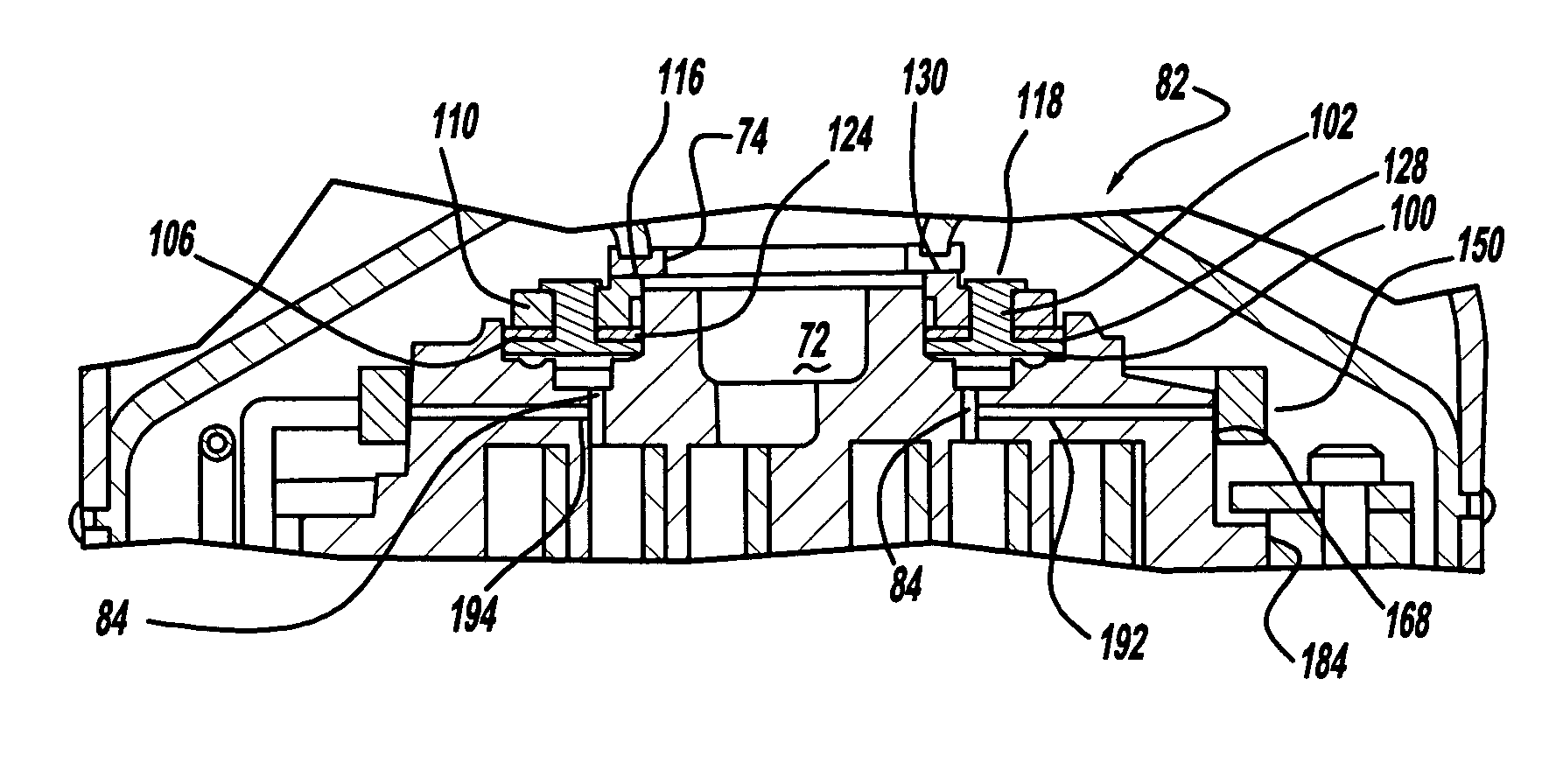
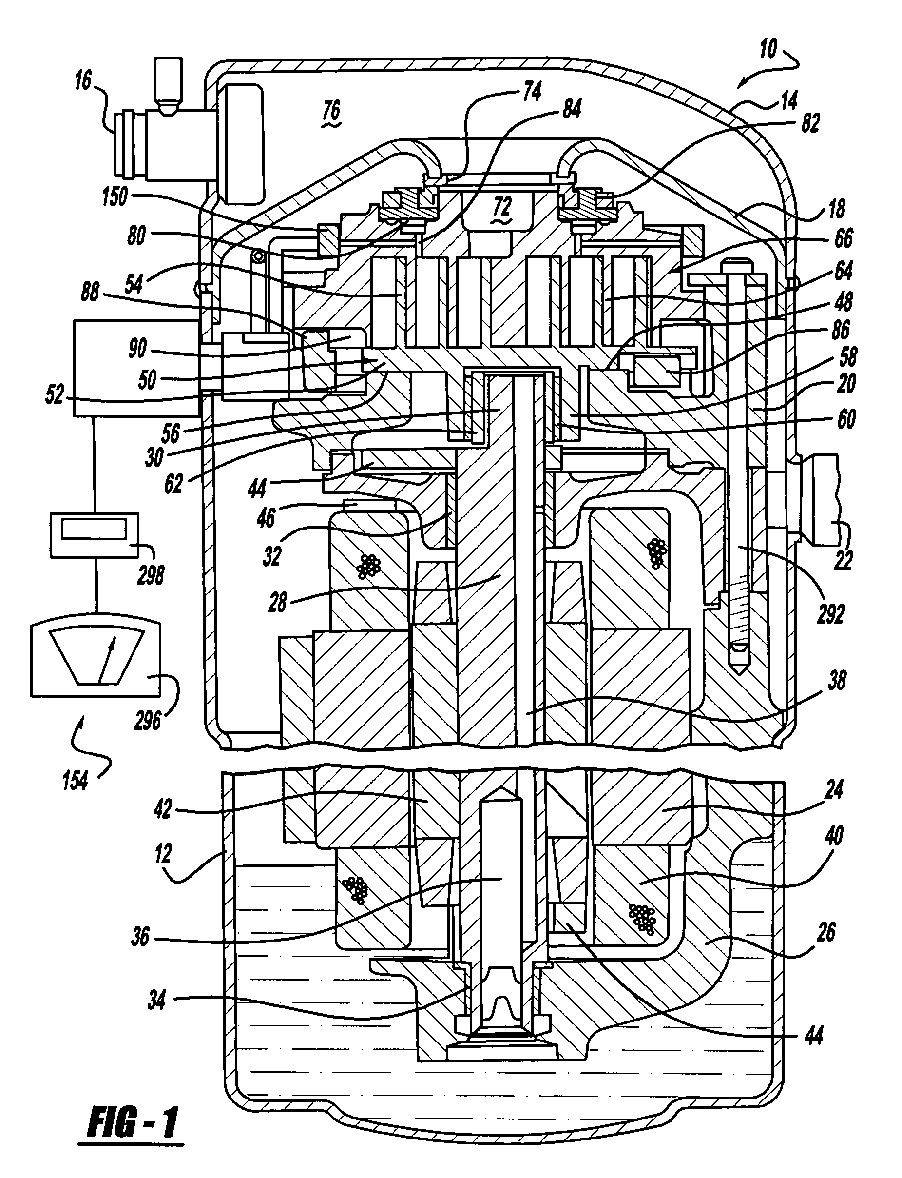
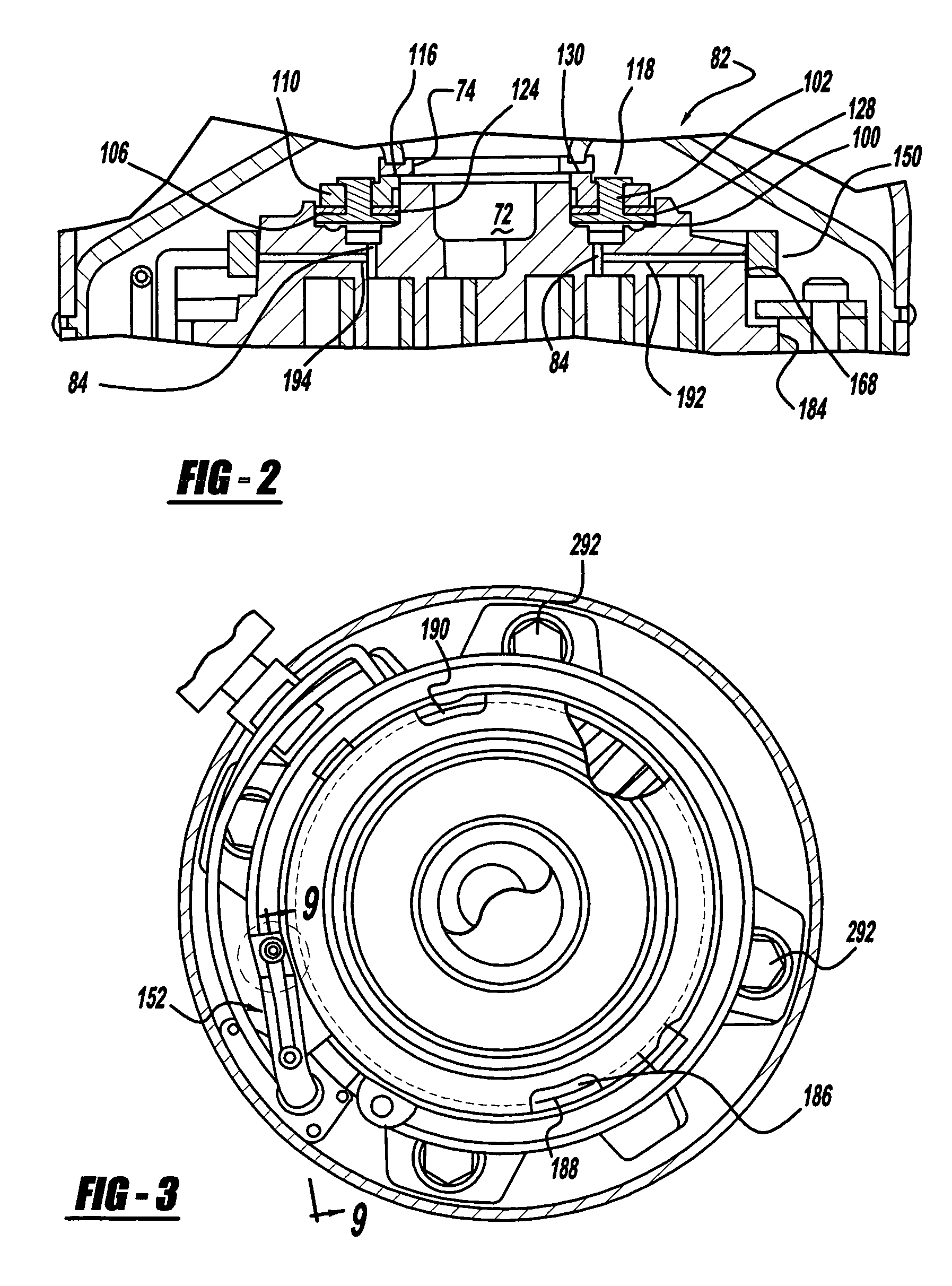
[0023] While the present invention is suitable for incorporation in many different types of scroll machines, including hermetic machines, open drive machines and non-hermetic machines, for exemplary purposes it will be described herein incorporated in a hermetic scroll refrigerant motor-compressor 10 of the “low side” type (i.e., where the motor and compressor are cooled by suction gas in the hermetical shell, as illustrated in the vertical section shown in FIG. 1). Generally speaking, compressor 10 comprises a cylindrical hermetic shell 12 which includes at the upper end thereof an end cap 14. End cap 14 is provided with a refrigerant discharge fitting 16 optionally having the usual discharge valve therein. Other elements affixed to the shell include a transversely extending partition 18 which is welded about its p...


PUM


Abstract

A scroll compressor has a biasing chamber which contains a pressurized fluid. The pressurized fluid within the chamber biases the two scroll members together. A rotatable ring is attached to one of the scroll members to open and close a passage leading to this biasing chamber. When the ring opens the passage in one embodiment, this releases the pressurized fluid to remove the load, biasing the two scroll members together. When the biasing load is removed, the two scroll members separate, creating a leakage path between discharge and suction to reduce the capacity of the scroll compressor. When the ring opens the passage in another embodiment, a delayed suction passage is opened to reduce the capacity of the compressor.

Description

FIELD OF THE INVENTION [0001] The present invention relates to capacity modulation of compressors. More particularly, the present invention relates to the capacity modulation of a scroll compressor by controlling the fluid pressure in a chamber where the fluid pressure in the chamber biases the two scrolls together. BACKGROUND AND SUMMARY OF THE INVENTION [0002] Capacity modulation is often a desirable feature to incorporate into the compressors of air conditioning and refrigeration systems in order to better accommodate the wide range of loading to which the systems may be subjected. Many different approaches have been utilized for providing this capacity modulation feature. These approaches have ranged from control of the suction inlet of the compressor to bypassing compressed discharge gas back into the suction pressure zone of the compressor. With a scroll-type compressor, capacity modulation has often been accomplished by using a delayed suction approach which comprises providi...

Claims


Application Information

Patent Timeline
IPC IPC(8): F04B49/00
CPCF04C18/0215F04C28/265F04C27/005F04C23/008
Inventor STOVER, CHRISTOPHER
Owner EMERSON CLIMATE TECH INC
Why Eureka
Try Eureka