Methods and apparatus for a wide area coordinated surveillance system

a surveillance system and wide area technology, applied in the field of surveillance systems and methods, can solve the problems of insufficient reliability of the approach to achieve a high level of security, tendency to nap or fall asleep, and inability to accurately fix the position, etc., to achieve the effect of simplifying the calibration complexity, and avoiding the formation of a large surveillance area

Active Publication Date: 2007-02-15
SIGHTLOGIX
View PDF7 Cites 298 Cited by
  • Summary
  • Abstract
  • Description
  • Claims
  • Application Information

AI Technical Summary

Benefits of technology

[0012] A surveillance system, in accordance with the present invention, uses a mixture of two different types of smart camera devices. The approach of the present invention provides for wide area continuous surveillance over a designated total surveillance region with a first level of resolution sufficient to detect moving objects and provide an approximate location of a detected target relying primarily upon a set of detection camera devices. The approach of the present invention also provides for a high resolution on demand capability controllable to a subset of designated smaller portions of the entire surveillance region, the designated smaller portions being controllable to include any or nearly any location within the entire surveillance region. The higher resolution imaging is output from tracking camera devices which can zero in on the target, e.g., using pan-tilt-zoom features of the camera, to obtain the high resolution image and facilitate target identification. At different times the high resolution areas will change, e.g., as a tracking camera device is assigned to confirm a detection camera device target or is following and tracking the movements of the target.
[0013] The surveillance system includes a first number of detection camera devices and a second number of controllable tracking camera devices, the composite of the detection camera devices providing full coverage of a designated total surveillance area. The second number of tracking camera devices is less than the first number of detection camera devices. In some embodiments, the ratio of detection camera devices to tracking camera devices is at least 4:1. In some embodiments, the ration of detection camera devices to tracking camera devices is at least 10:1. The number of each type of camera device that is employed is typically dictated by the particulars of each individual area undergoing surveillance. In some embodiments, the cameras in the detection camera devices are less expensive, have lower resolution, and / or have lower capabilities than the cameras in the tracking camera devices. This coordinated on-demand target imaging method relieves the need for deploying expensive cameras everywhere. The tracking camera devices are strategically located such that the set of tracking cameras can be controllably positioned and adjusted to view the entirety of the area or substantially the entirety of the area covered by the set of detection camera device. The tracking camera devices typically include pointing direction capability, e.g., rotary and tilt control, and focusing control, e.g., zoom in / zoom out control for changing the focal length.
[0017] In accordance, with another feature of some embodiments, of the present invention, the control system is able to maintain full or nearly full detection coverage should one of the detection camera devices fail. By temporarily reassigning one tracking camera device, or more than one tracking camera device used in combination, to be positioned and focus set to cover the same area that would normally be covered by the failed detection camera device, overall coverage is maintained. In such a situation, the reassigned tracking camera device would not be used for target confirmation and would not be controlled to zoom in on and follow a target, but would rather temporarily serve to provide initial target detection and locate the target based on target position within a fixed field of view. Under such a scenario, the centralized control system units would change the criteria for sending an alert and sending compressed video to the guard interface unit for such a coverage region so that a single camera detection would result in an alarm and the forwarding of video. This approach, in accordance with the present invention, provides a graceful degradation of overall capabilities in a limited region, while yet maintaining full or nearly full coverage for the entire surveillance area.
[0020] Target size is an important parameter for target discrimination. In some embodiments, the camera devices can determine target size based on a 3 dimensional model. This approach of using a 3D model is advantageous because the terrain in a large surveillance area can be very uneven. In some embodiments, the surveillance system automatically constructs the 3D model as part of a built in functionality during system installation which simplifies calibration complexity.
[0021] Another feature of some embodiments of the present invention is the use of a portable coordinate system, e.g., a GPS coordinate system. Each of the elements in the system, as well as guards investigating a target detection, can interchange data / information associated with the same target and the data / information can be processed, e.g., obtaining a more precise position fix using data / information from multiple cameras, e.g., using triangulation techniques. By providing geo-spatial information that can be visualized on a sitemap and associated with universally recognizable GPS coordinates, an investigating guard can be quickly and efficiently directed to the target.

Problems solved by technology

This approach is not reliable enough to achieve a high level of security, as guards hired to look at monitors all day long have a tendency to fall asleep, e.g., due to boredom.
In some cases, the guards, who are not necessarily highly paid, have taken on the security guard job as a second job, and have a tendency to nap or fall sleep when left alone.
In some cases, guards become pre-occupied with other distractions, e.g., newspapers, magazines, talking on the phone, watching or listening to a ball game, receiving a delivery package, etc., and may be distracted at a critical moment missing a security breach.
A single guard is limited as to how many monitors he / she can simultaneously view effectively before becoming overloaded.
However, this approach is costly and still not highly reliable, since for the approach to achieve highly effective coverage all the guards need to continuously remain vigilant, an unlikely scenario.
Another approach employed is to use a limited number of guards and switch between cameras; however, this results in incomplete continuous coverage increasing the likelihood of an undetected security breach.
Although it might seem that replacing humans with a fully computerized system might seem to be a viable alternative to increasing reliability and overall effectiveness, there is another problem which results.
In some other known surveillance systems, closed circuit television cameras are installed and connected to recording devices which tape the camera video; however, a guard is not stationed to continuously monitor the video.
Such an approach is useful for forensic crime detection, but is not well suited for identifying the security breach in real-time and being able to take actions to stop the criminal activity.
In view of the Sep. 11, 2001 terrorist events and other worldwide terrorist activities, the reliability of the above described approaches is unacceptable for many critical sites.
Cost effective approaches would be attractive for deployment at other sites where security is needed, but the level of security required is not quite as high, e.g., an office, store, or home site.
Typically, this has required a large number of expensive cameras to cover a small section to obtain enough resolution and a very large number of expensive cameras to cover a large area.
This approach can become economically infeasible for many deployments.
Another problem with a large number of cameras is the issue of bandwidth.
Continuous closed circuit television streamed back to a guard site for a large number of cameras, e.g., via dedicated cables or over wireless air links tends to consume a lot of bandwidth, which may not be available or may be very costly.
Another problem with a surveillance system including a large number of cameras is the reliability issue.
As the number of cameras in the system increases, it becomes more likely that at any given time a camera will have failed and be inoperative somewhere in the system, resulting in an uncovered surveillance region.
However, this approach becomes very expensive, and is infeasible in many applications from a cost perspective.
Individually designing and integrating such a custom system can be very labor intensive and tends to contribute to system unreliability, as each custom system when deployed has no past track record of operation, and it is to be expected that bugs and deficiencies in the design will show up during operation.

Method used


Image

  • Methods and apparatus for a wide area coordinated surveillance system
  • Methods and apparatus for a wide area coordinated surveillance system
  • Methods and apparatus for a wide area coordinated surveillance system

Examples


Embodiment Construction

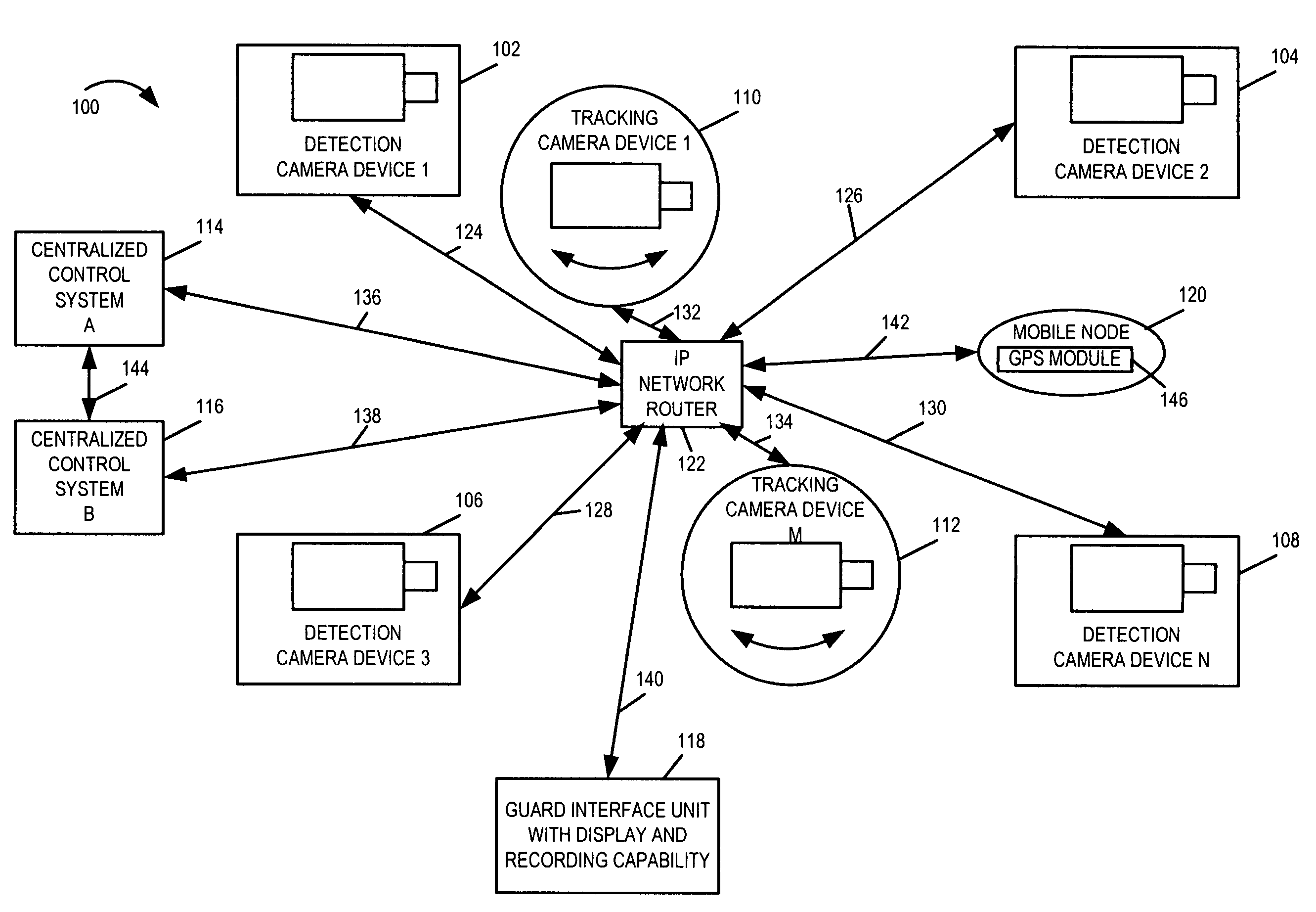
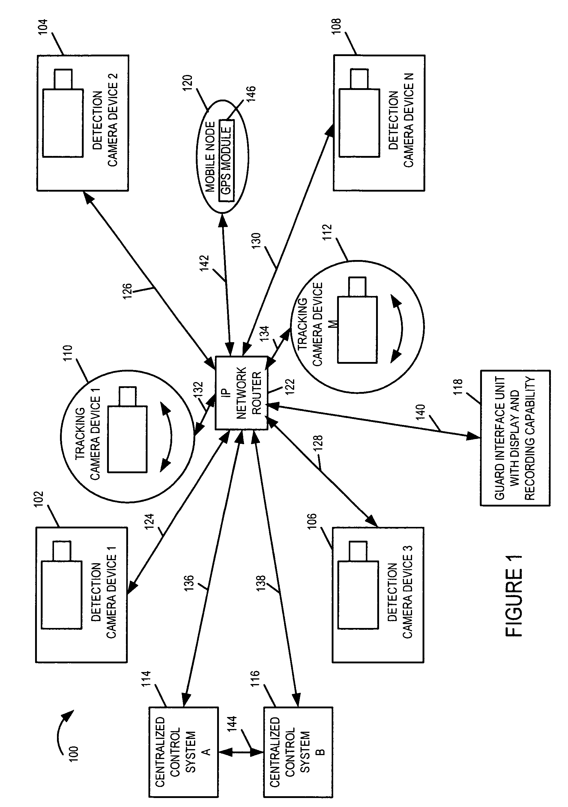
[0034]FIG. 1 is a drawing of an exemplary automated threat detection and tracking system 100 implemented in accordance with the present invention and using methods of the present invention. Exemplary system 100 includes a plurality of detection camera devices (detection camera device 1102, detection camera device 2104, detection camera device 3106, detection camera device N 108), a plurality of tracking camera devices (tracking camera device 1110, tracking camera device M 112), two centralized control systems (centralized control system A 114, centralized control system B 116), a guard interface unit 118, a mobile node 120, and an IP network router 122. The various devices (102, 104, 106, 108, 110, 112, 114, 116, 118, 120) are coupled to IP network router 122 via communication links (124, 126, 128, 130, 132, 134, 136, 138, 140, 142), respectively, allowing the various devices to communicate with one another and interchange data / information.

[0035] Exemplary system 100 is an integrat...


PUM


Abstract

A coordinated surveillance system uses a larger number of fixed low resolution detection smart camera devices and a smaller number of pan / tilt / zoom controllable high resolution tracking smart camera devices. The set of detection cameras provide overall continuous coverage of the surveillance region, while the tracking cameras provide localized high resolution on demand. Each monitor camera device performs initial detection and determines approximate GPS location of a moving target in its field of view. A control system coordinates detection and tracking camera operation. A selected tracking camera is controlled to focus in on, confirm detection, and track a target. Based on a verified detection, a guard station is alerted and compressed camera video is forwarded to the guard station from the camera(s). The guard station can direct a patrol guard to the target using GPS coordinates and a site map. Redundancy is provided by using multiple control units, each able to handle the full load in the event of failure. Camera devices vote on the status of the control units. A failed detection camera device can be temporarily replaced by a tracking camera device in a back-up mode of operation thus maintaining full overall basic coverage of the surveillance region.

Description

FIELD OF INVENTION [0001] The present invention relates generally to systems and methods for surveillance, and more particularly to systems and methods for wide area coordinated surveillance systems using a mixture of different smart camera devices. BACKGROUND [0002] Many known surveillance systems have used a closed circuit television approach. In such an approach, a number of video cameras are mounted at different points; video coaxial cable is routed from each of the cameras to a centralized guard station; the outputs of the cameras are fed to video display monitors at the guard station. A guard typically monitors the closed circuit television displays in real time. The outputs of the video cameras may also be recorded on a tape which is typically overwritten after some specified amount of time. This approach relies on human monitoring of the closed circuit television displays to detect breaches in security. A guard is hired to sit at the guard station and continuously monitor mu...

Claims


Application Information

Patent Timeline
Patent Type & Authority Applications(United States)
IPC IPC(8): H04N7/173H04N7/18
CPCG08B13/19608G08B13/19643G08B13/19656G08B13/19663H04N21/6587H04N7/17318H04N7/181H04N21/4223H04N21/47202H04N5/247H04N5/77H04N23/90
Inventor ROMANOWICH, JOHN FREDERICKCHIN, DANNYCLEARY, GEOFFREY ALAN
Owner SIGHTLOGIX
Why Eureka
Try Eureka