Secondary Air Injector For Use With Exhaust Gas Simulation System

a technology of exhaust gas simulation and second air injector, which is applied in the direction of combustion types, lighting and heating apparatus, instruments, etc., can solve the problems of inconvenient use of real engines for long-term testing, high maintenance costs, and inability to conveniently permit the separate evaluation of individual variables of real engines

Inactive Publication Date: 2007-02-22
SOUTHWEST RES INST
View PDF63 Cites 11 Cited by
  • Summary
  • Abstract
  • Description
  • Claims
  • Application Information

AI Technical Summary

Problems solved by technology

However, the use of a real engine for long term testing can be inconsistent, maintenance intensive, and expensive to operate.
In addition, a re...

Method used


Image

  • Secondary Air Injector For Use With Exhaust Gas Simulation System
  • Secondary Air Injector For Use With Exhaust Gas Simulation System
  • Secondary Air Injector For Use With Exhaust Gas Simulation System

Examples


Embodiment Construction

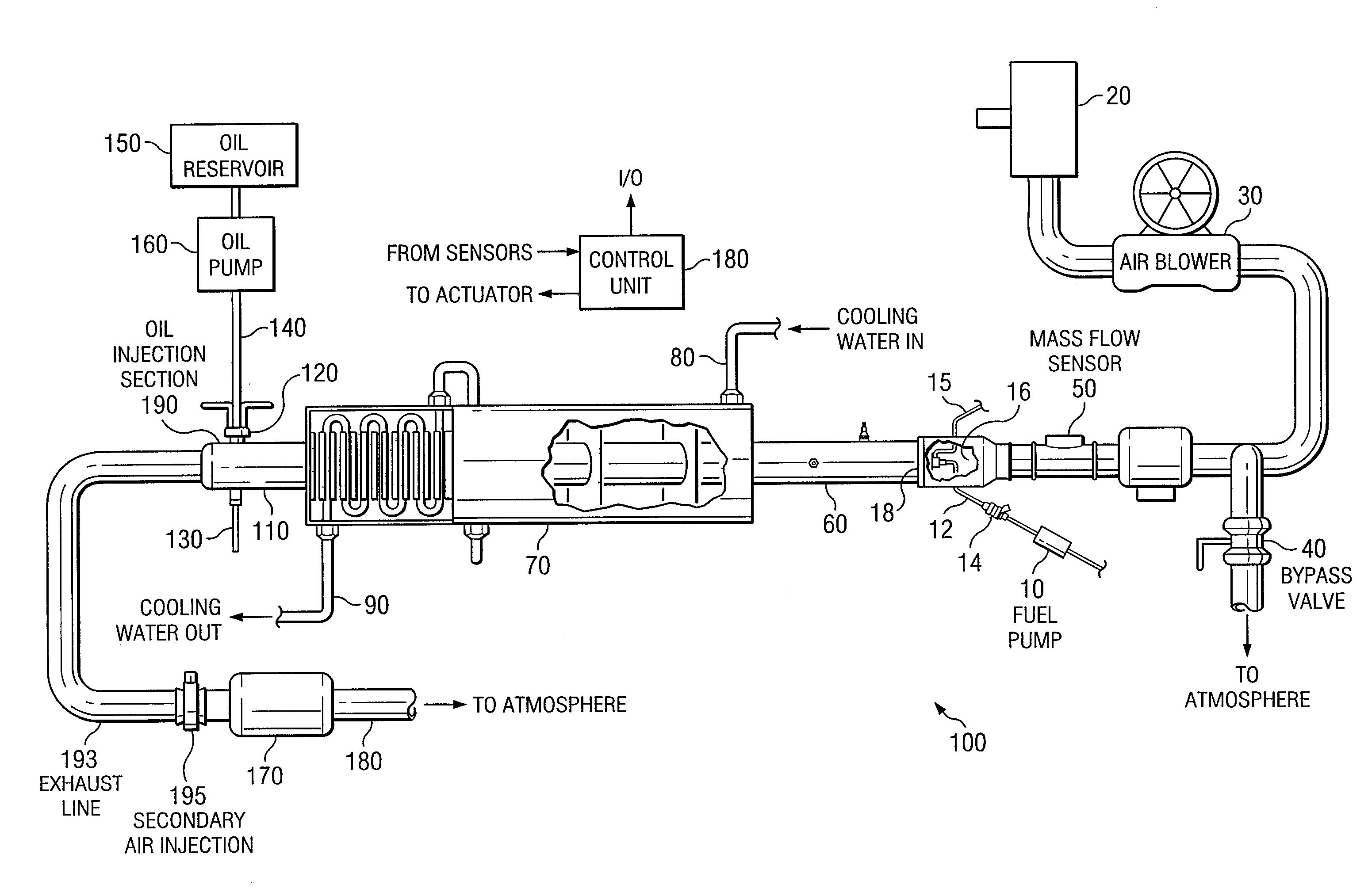
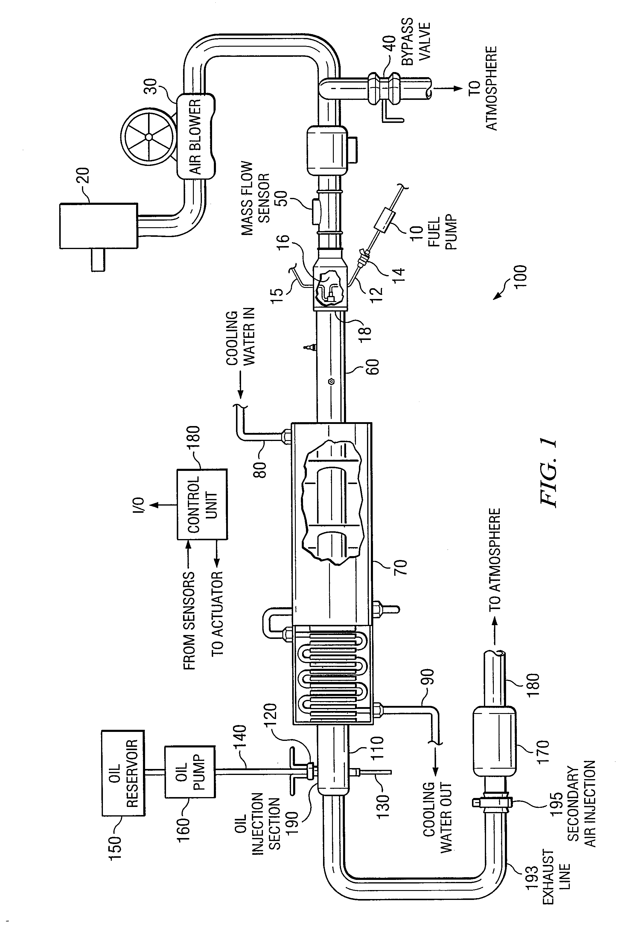
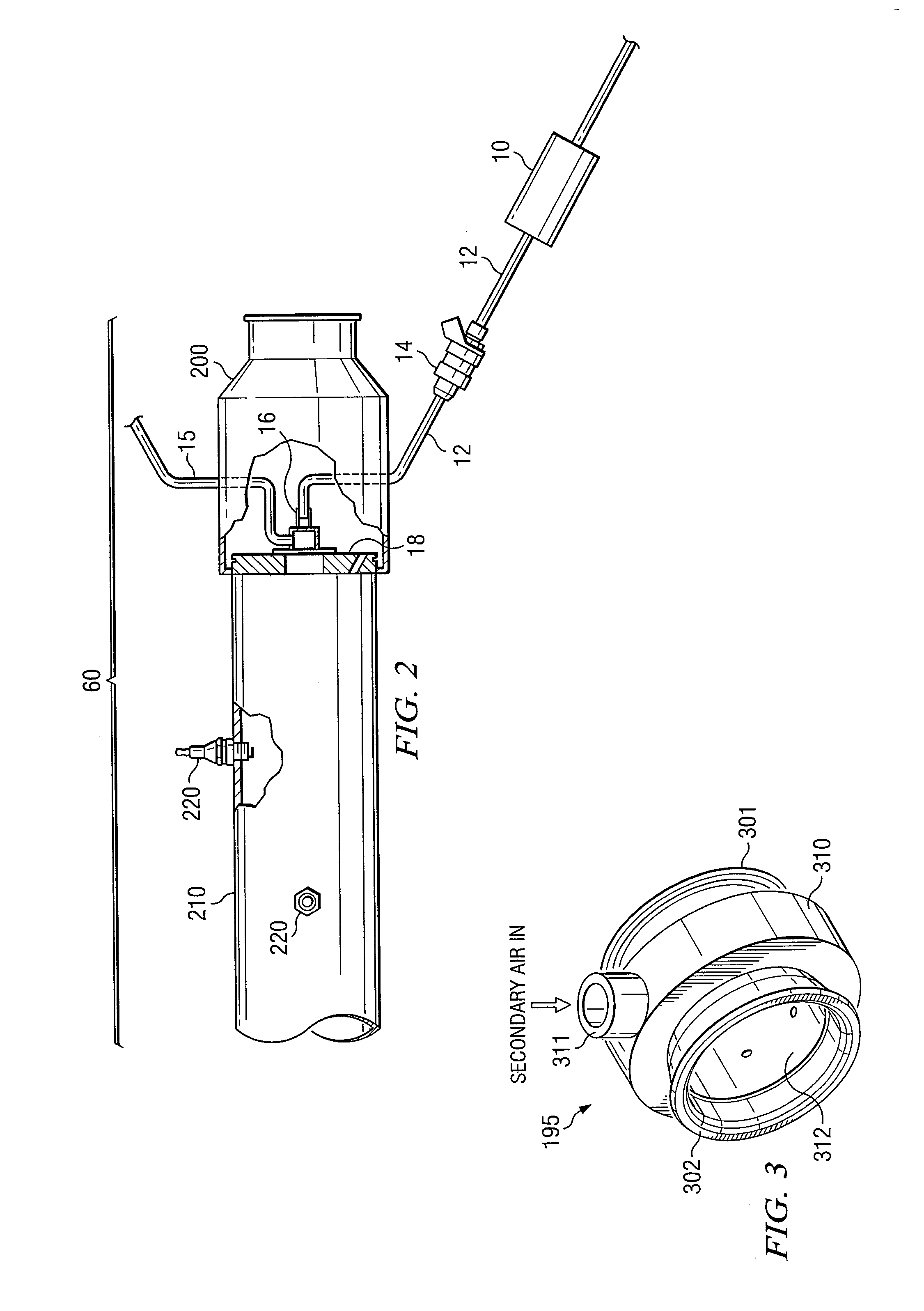
[0011] The following description is directed to a burner-based exhaust flow simulation system, which produces a flow of exhaust gas with a composition and temperature corresponding to the exhaust flow produced by an internal combustion engine. The system can be used with or without introducing oil to simulate engine oil consumption.

[0012] As an example of one application of the system, an emissions control device can be installed on the exhaust line downstream of the burner. The effect of extended driving conditions and elevated temperatures on the emissions control device can be simulated. The system can also simulate the effects of additives and contaminants from the engine. The system is capable of “aging” the emissions control device, which can then be evaluated, and if desired, performance tested on an actual vehicle.

[0013] Other applications of the exhaust flow simulation system are possible. Various sensors, such as those used for emissions monitoring and control, can be te...


PUM


Abstract

A secondary air injector for use with an exhaust flow simulation system. A typical exhaust flow simulator is a burner-based system, in which exhaust from a combustive burner is exhausted through an exhaust line. The secondary air injector is placed downstream the burner to create a desired thermal condition or composition of the exhaust gas. The injector comprises a hollow ring fitted around the exhaust line, with multiple holes for evenly injecting the air into the exhaust line.

Description

RELATED PATENT APPLICATION [0001] This application claims the benefit of U.S. Provisional Application No. 60 / 705,930, filed Aug. 5, 2005 and entitled “Secondary Air Injector for Use with Exhaust Flow Simulation System”.TECHNICAL FIELD OF THE INVENTION [0002] The present application relates in general to systems for simulating the exhaust flow of an engine under extended driving conditions and elevated temperatures. BACKGROUND OF THE INVENTION [0003] As a result of stricter regulations for automotive emissions, it was desired to design a testing apparatus and procedure for testing emissions control devices. Historically, actual internal combustion engines have been used for such evaluations. However, the use of a real engine for long term testing can be inconsistent, maintenance intensive, and expensive to operate. In addition, a real engine does not conveniently permit the separate evaluation of individual variables, such as the effects of various constituents of fuel and oil. [0004...

Claims


Application Information

Patent Timeline
IPC IPC(8): G01M19/00G01M99/00
CPCF01N3/30F23C7/02F23D2900/21006F23D99/00F23D99/003F23C2201/102F23D91/02
Inventor TIMMONS, SUZANNE ANNETTEWEBB, CYNTHIA C.
Owner SOUTHWEST RES INST
Why Eureka
Try Eureka