Deactivating roller finger follower

a roller finger follower and deactivating technology, applied in the direction of valve arrangements, instruments, mechanical control devices, etc., can solve the problems of poor manufacturing tolerance, long-term wear, and inability to reliably deactivate the known deactivating rocker arm assembly

Inactive Publication Date: 2007-02-22
KOYO BEARINGS USA
View PDF16 Cites 86 Cited by
  • Summary
  • Abstract
  • Description
  • Claims
  • Application Information

AI Technical Summary

Benefits of technology

[0007] In accordance with one aspect of the present invention, a deactivating roller follower assembly for deactivating an associated poppet valve for an internal combustion engine includes a body including a valve end, a pivot end, and a plunger bore. The valve end of the body is configured to contact the associated poppet valve and the pivot end of the body is configured to contact a pivot of the associated internal combustion engine. The assembly further includes a pivotable arm including a hinged end and a free end. The hinged end is rotatably mounted to the valve end of the body. The free end includes a curvilinear engaging surface for trans

Problems solved by technology

However, a common problem involves the reliability of known deactivating rocker arm assemblies to consistently activate or deactivate a given valve upon demand.
The root cause of these failures typically involve the latching components that are responsible for engaging an oscillating finger, lever, or arm and transmitting the high load forces generated by a rotating cam lobe to the stem of a valve.
In some cases, the failure can be attributed to a misal

Method used


Image

  • Deactivating roller finger follower
  • Deactivating roller finger follower
  • Deactivating roller finger follower

Examples


first embodiment

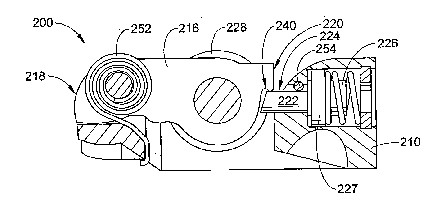
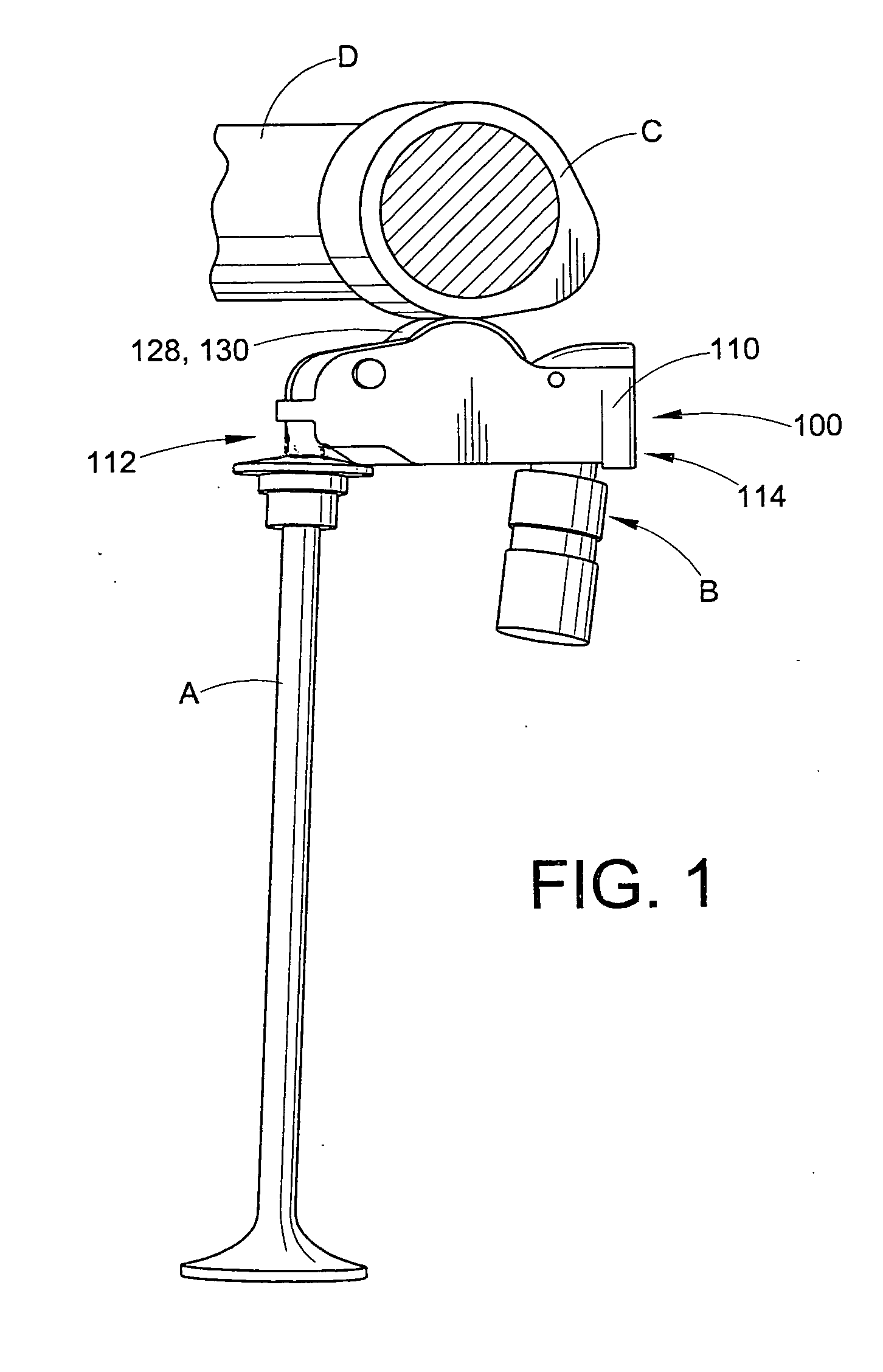
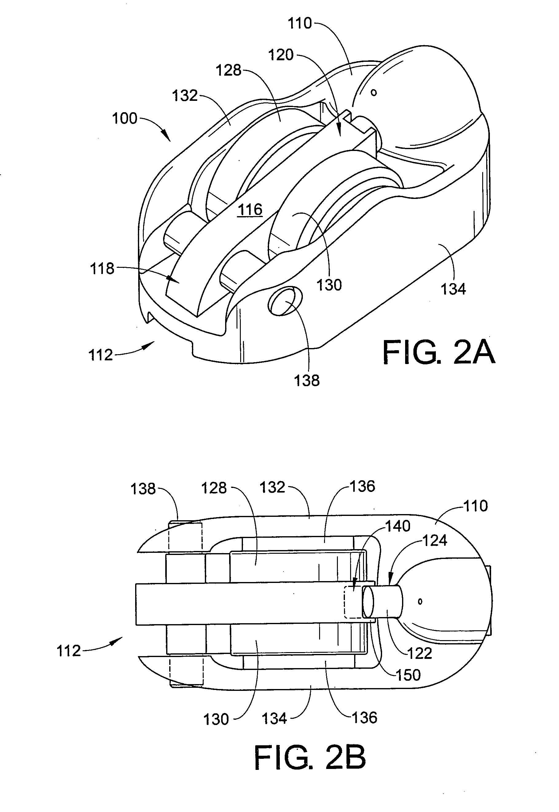
[0021] With reference to FIGS. 1-4, a deactivating roller finger follower (DRFF) assembly 100 is shown. The assembly 100 generally includes a body or housing 110 having a valve end 112 and a pivot end 114. The assembly 100 also includes an arm 116 having a hinged end 118 and a free end 120. A plunger 122 is disposed in the pivot end 114 of the body 110 and includes a latching end 124 and a piston end 126.

[0022] With particular reference to FIG. 1, the DRFF assembly is shown in a working configuration. As shown, a stem portion of a poppet valve A engages the valve end 112 of the body 110. In addition, the pivot end 114 is shown supported by a rocker pivot or hydraulic lash adjuster B. Along an upper portion of the assembly 100, a cam lobe C of a cam shaft D is shown in rolling contact with the first and second roller bearings 128, 130. During normal engine operation, the camshaft D and cam lobe C rotate urging a first and second roller bearing 128, 130 in a downward direction. Since ...

third embodiment

[0034] A distinction between the third embodiment and the previous embodiments involves the use of an anti-rotation shoulder 354 on the piston end 326 of the plunger 322. The anti-rotation shoulder 354 shown in FIGS. 9-11 includes a semi-circular or D-shaped cross section such that it includes an upper flat surface. The D-shaped anti-rotation shoulder 354 slidably engages a similar D-shaped aperture 356 in the retainer member 348. Because the cross section of the shoulder 354 is non-circular and since the shoulder 354 engages a non-circular aperture 356, the shoulder 354 and plunger 322 are prevented from rotating within the first and second plunger bores 342,343. Of course, the cross section of the anti-rotation shoulder 354 may be of any other non-circular regular or irregular geometry (such as square, triangular, rectangular, etc). Because the plunger 322 is prevented from rotating about the longitudinal axis of the assembly 300 once again ensures that the upper flat engaging sur...


PUM


Abstract

A deactivating roller follower assembly for deactivating an associated poppet valve for an internal combustion engine includes a body including a valve end, a pivot end, and a plunger bore. The valve end of the body is configured to contact the associated poppet valve and the pivot end of the body is configured to contact a pivot of the associated internal combustion engine. The assembly further includes a pivotable arm including a hinged end and a free end. The hinged end is rotatably mounted to the valve end of the body. The free end includes a curvilinear engaging surface for transmitting a force required to activate the associated poppet valve. In addition, the assembly includes a plunger including a latching end and a piston end. The plunger is disposed in the plunger bore in the pivot end of the body. The plunger moves between an extended position and a retracted position. The latching end of the plunger selectively engages the free end of the arm to place the arm in a latched state, whereby preventing the arm from moving relative to the body. And, the latching end of the plunger selectively disengages the free end of the arm to place the arm in an unlatched state, whereby permitting the arm to move relative to the body.

Description

[0001] A claim for domestic priority is made herein under 35 U.S.C. §119(e) to U.S. Provisional App. Ser. No. 60 / 705,405 filed on Aug. 4, 2005, the entire disclosure of which is incorporated herein by reference.BACKGROUND [0002] The present invention relates generally to the field of engine systems having valve trains capable of being deactivated hydraulically. It finds particular application in conjunction with deactivating roller followers used to deactivate individual valves in an internal combustion engine and will be described with particular reference thereto. It will be appreciated, however, that the invention is also amenable to other like applications. [0003] Deactivating rocker arm assemblies are generally known in the art for their use in internal combustion engines and are typically used to deactivate exhaust and intake valves. This is done as part of an overall strategy to selectively deactivate one or more combustion chambers (or cylinders) of the engine to conserve fu...

Claims


Application Information

Patent Timeline
IPC IPC(8): F02B75/18
CPCF01L1/185F01L1/2405Y10T74/20882F01L2105/00F01L2001/186F01L13/0005F01L2001/467F01L2305/00
Inventor DEIERLEIN, MATTHEW J.
Owner KOYO BEARINGS USA
Why Eureka
Try Eureka