Chip reversing device and chip reversing method, and chip mounting apparatus and chip mounting method

a technology of reversing device and mounting apparatus, which is applied in the direction of metal working apparatus, chemistry apparatus and processes, manufacturing tools, etc., can solve the problems of obstructing the efficient chip mounting action and action interference, and achieve the effect of efficient chip mounting action

Inactive Publication Date: 2007-02-22
PANASONIC CORP
View PDF3 Cites 11 Cited by
  • Summary
  • Abstract
  • Description
  • Claims
  • Application Information

AI Technical Summary

Benefits of technology

[0036] According to the invention, there is adopted the constitution, in which the chip is placed and held on the chip holding unit in the upward position, and in which the reversing member is turned downward on the reversal shaft to reverse the chip held on the chip holding unit, vertically. Therefore, the reversing member is prevented from protruding upward of the height level for the chip transfer so that the interference with the chip pick-up head or the chip mounting head can be eliminated to make the chip mounting action efficient.

Problems solved by technology

Depending upon the settings of the action timings of the individual units of the apparatus, therefore, an action interference may occur among the holding head being turned, a chip extract / transfer head for picking up the chip from the chip feed unit and placing it on the turning mechanism, and a chip mount unit for mounting the reversed chip transferred, on the substrate.
In order to prevent that interference, moreover, the timing, at which the chip extract / transfer head or the chip mounting head can make access to the reversing mechanism, is restricted to obstruct an efficient chip mounting action.

Method used


Image

  • Chip reversing device and chip reversing method, and chip mounting apparatus and chip mounting method
  • Chip reversing device and chip reversing method, and chip mounting apparatus and chip mounting method
  • Chip reversing device and chip reversing method, and chip mounting apparatus and chip mounting method

Examples


embodiment 1

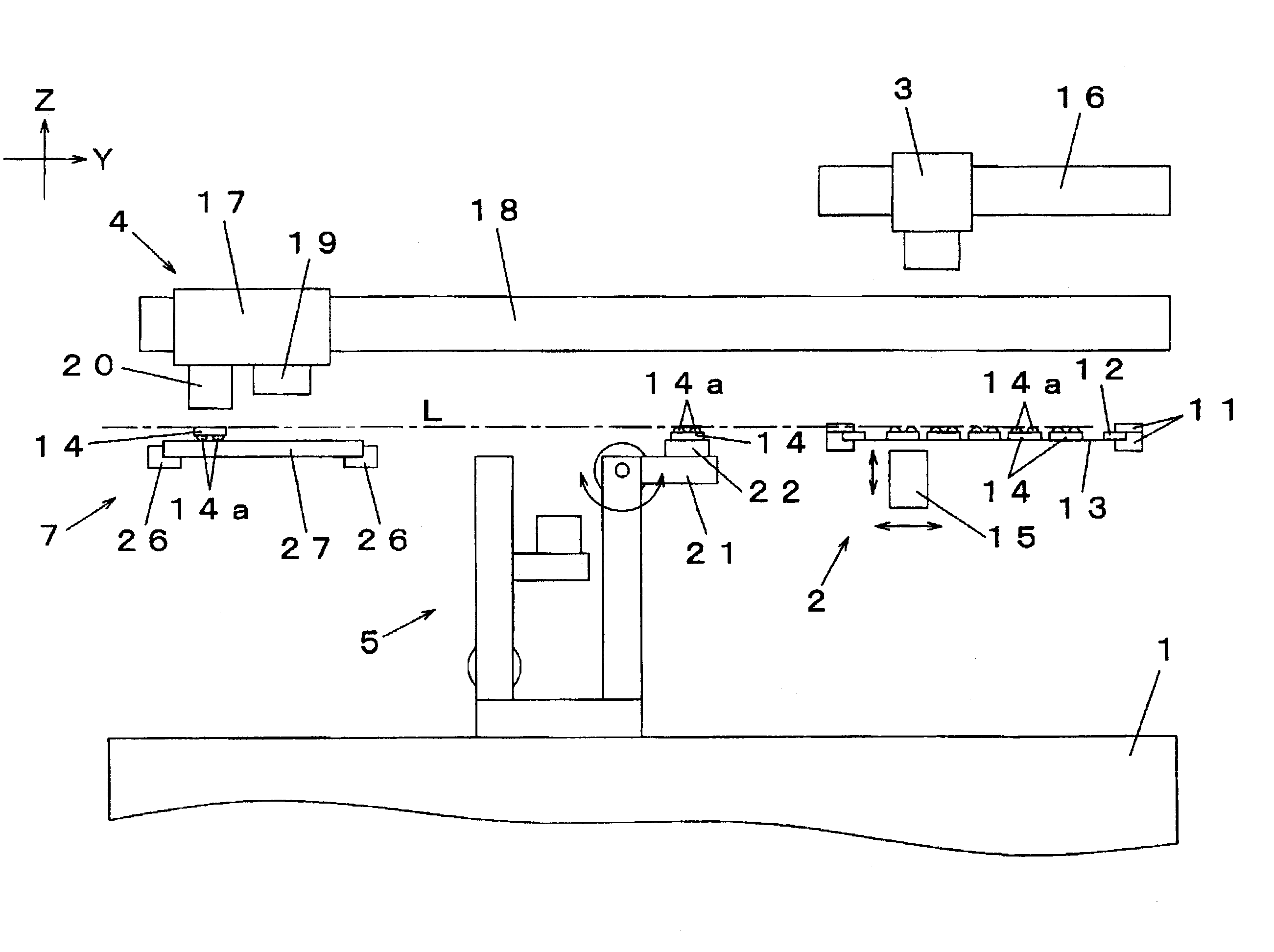
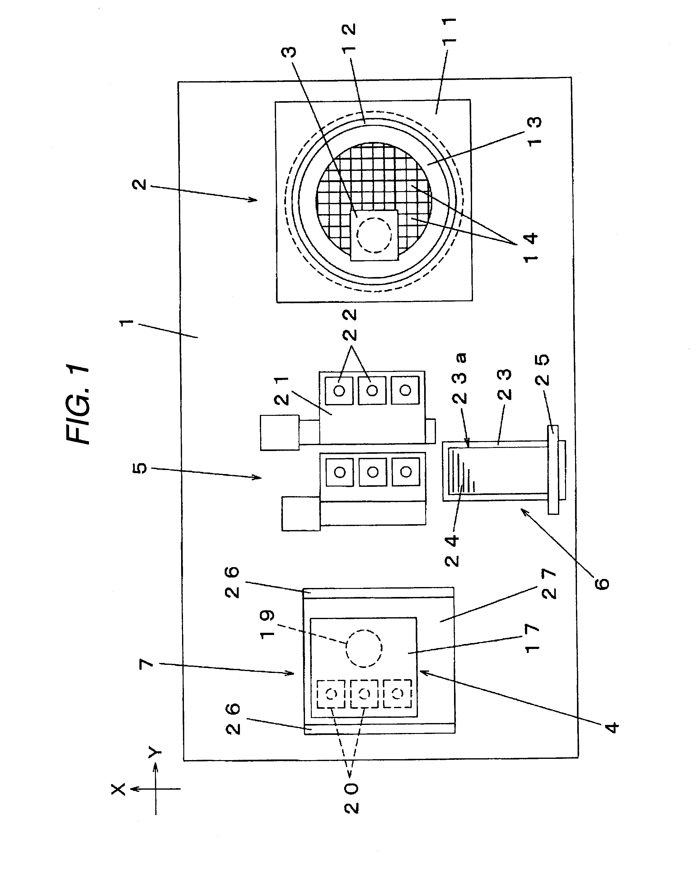
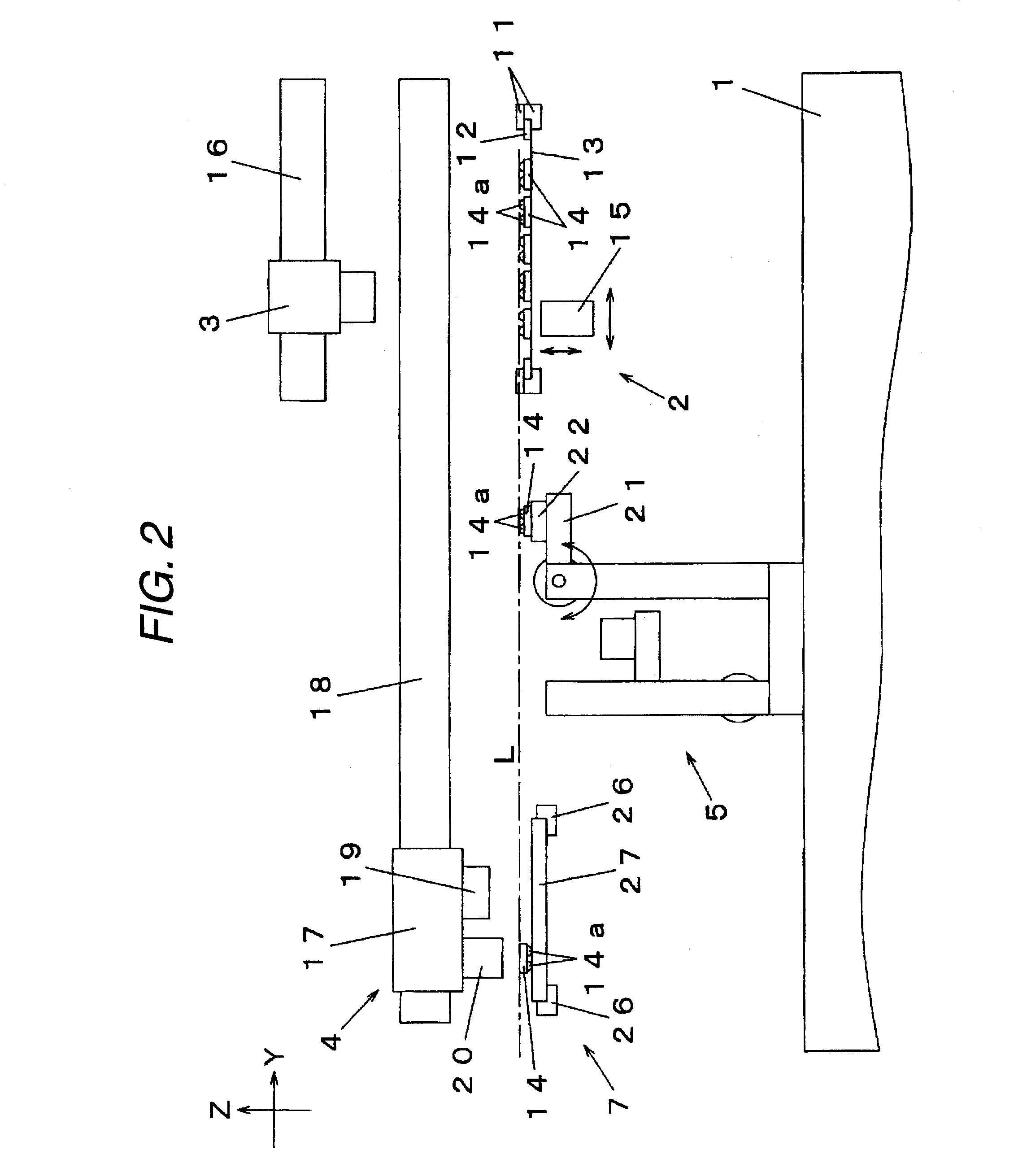
[0053]FIG. 1 is a top plan view of a chip mounting apparatus of Embodiment 1 of the invention; FIG. 2 is a side elevation of the chip mounting apparatus of Embodiment 1 of the invention; FIGS. 3A and 3B present structure explaining diagrams of a parts inversion stage in the chip mounting apparatus of Embodiment 1 of the invention; FIGS. 4A through 4C present action explaining diagrams of the parts inversion stage in the chip mounting apparatus of Embodiment 1 of the invention; and FIGS. 5A through 10B are action explaining diagrams of chip mounting actions in Embodiment 1 of the invention.

[0054] At first, the entire structure of the chip mounting apparatus is described with reference to FIG. 1 and FIG. 2. This chip mounting apparatus has functions to reverse chip parts having connecting electrodes or bumps formed on one side face, up-side-down, and to mount the reversed chip parts on a substrate by a mounting head 17. On a base 1, as shown in FIG. 1 and FIG. 2, there are arranged i...

embodiment 2

[0087]FIGS. 11A through 16 are action explaining diagrams of chip mounting actions in Embodiment 2 of the invention. In Embodiment 2, too, the chip, as fed by the chip feed unit 2, is vertically reversed and mounted on the substrate 14 held on the substrate holding unit 7 by using a chip mounting apparatus like that of Embodiment 1. In the following individual drawings, the components, as thought to need no explanation, of the apparatus are also suitably omitted from the drawings, and the illustration of the bumps 14a is omitted from the chips 14.

[0088] At first, FIG. 11A through FIG. 12B show the chip holding step, as shown in FIGS. 5A through 6B in Embodiment 1, at which the chip 14 is picked up from the chip feed unit 2 by the chip pick-up / transfer device and is placed and held on the chip holding unit 22 of the chip reversing device 5. Next, the reversing step of reversing the chip 14 held on the chip holding unit 22, vertically by the chip reversing device 5, is executed. Spec...


PUM

PropertyMeasurementUnit
heightaaaaaaaaaa
structure explainingaaaaaaaaaa
structureaaaaaaaaaa

Abstract

In a chip reversing device used in a chip mounting apparatus for holding and vertically reversing a chip placed by a bonding nozzle, the chip is held on a chip holding unit disposed in a reversing member and is vertically reversed by turning the reversing member downward on an reversal shaft. After the reversed chip was received by a chip receiving unit, this chip receiving unit is lowered to a retracted position to return the reversing member to an original position. In this state, the chip receiving unit is raised to position the chip at a height level L for a chip transferring action. As a result, the reversing member does not protrude to above the height level for the chip transfer thereby to interfere with another mechanism, so that the chip mounting actions can be made efficient.

Description

BACKGROUND OF THE INVENTION [0001] 1. Field of the Invention [0002] The present invention relates to a chip reversing device and a chip reversing method for reversing a chip, and a chip mounting apparatus and a chip mounting method for reversing and mounting a chip on a substrate. [0003] 2. Related Art [0004] In a chip mounting apparatus for mounting chip parts such as semiconductor chips on a substrate, the mounting actions to hold the chip, as picked up from a chip feed unit, on a mounting head and to mount the picked-up chip on the substrate are repeatedly performed. The parts such as a flip chip, in which bumps or connecting protrusion electrodes are formed on one side face, are generally fed in the bump-formed faces positioned upward, and the chips, as picked up from the chip feed unit, are reversed up-side-down and are mounted on the substrate with the bump-formed face being directed downward. As this chip mounting apparatus for the parts needing the vertical inversions after ...

Claims


Application Information

Patent Timeline
Patent Type & Authority Applications(United States)
IPC IPC(8): B32B37/00H01L21/00B32B38/00B32B38/18
CPCH01L21/67144Y10T29/53478Y10T156/1702Y10T29/53174Y10T29/49131Y10T29/4913Y10T29/49133H05K13/04
Inventor MAKINO, YOICHIKABESHITA, AKIRA
Owner PANASONIC CORP
Why Eureka
Try Eureka