Control for a heating and/or cooling unit

Active Publication Date: 2007-02-22
COPELAND COMFORT CONTROL LP
View PDF9 Cites 70 Cited by
  • Summary
  • Abstract
  • Description
  • Claims
  • Application Information

AI Technical Summary

Benefits of technology

[0003] The present invention relates to a heating and cooling unit for a space, and a control for establishing operation of the heating and cooling unit to provide conditioned air to the space. In one embodiment, the control is mo

Problems solved by technology

However, such thermostats require routing of low voltage wiring from the heating or cooling unit to where the thermostat is mounted in the space, an

Method used


Image

  • Control for a heating and/or cooling unit
  • Control for a heating and/or cooling unit
  • Control for a heating and/or cooling unit

Examples


Embodiment Construction

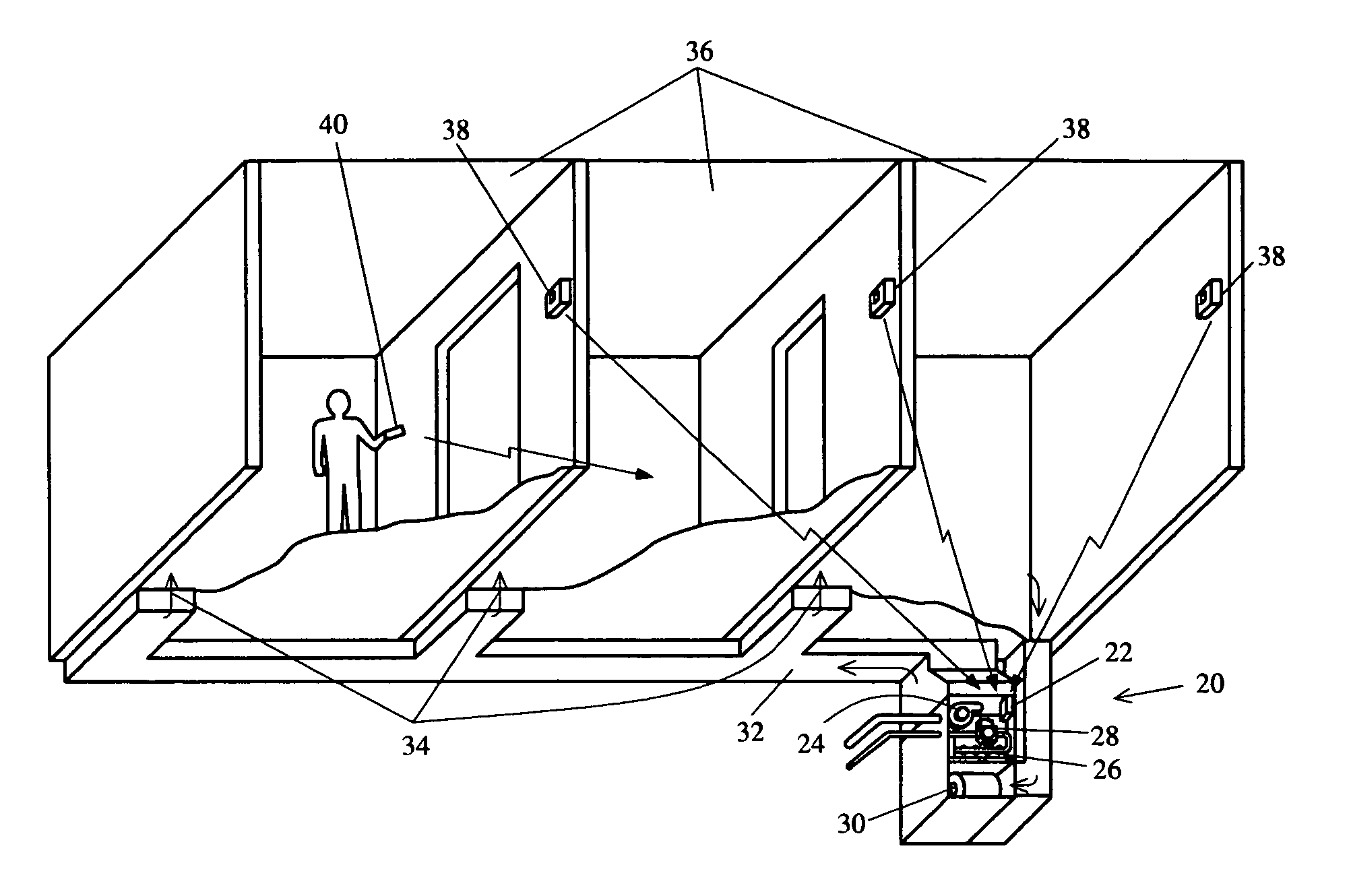
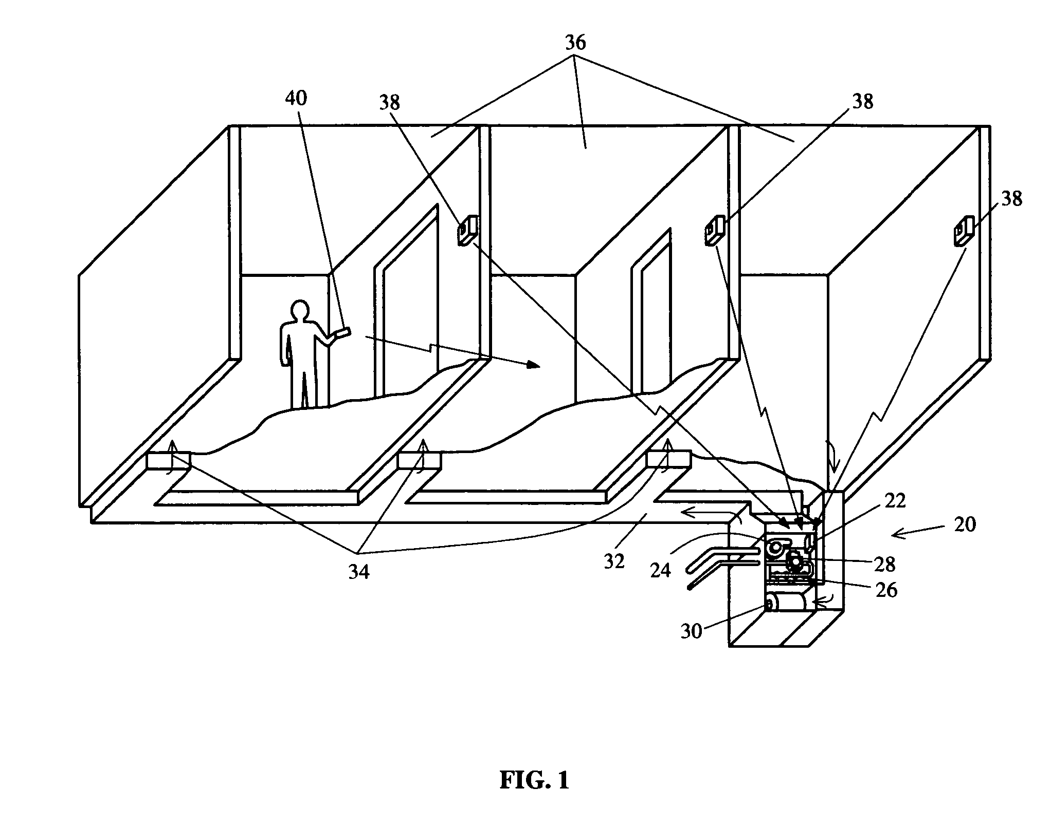
[0010] One embodiment of a climate control system according to the principles of the present invention is shown in FIG. 1. The climate control system comprises a heating and cooling unit 20 for supplying conditioned air to a space is provided that comprises one or more remote temperature sensors 38 for transmitting one of a sensed temperature for the space, a heating set point temperature, or a cooling set point temperature, wherein the one or more remote sensors 38 are incapable of switching on a heating or cooling system. The climate control system comprises a combustion air blower 24 for providing combustion air to a burner 26, an igniter for igniting gas, a gas valve 28 for permitting gas flow to a burner to provide for heating operation, and a circulating air blower 30 for circulating conditioned air in the space to provide heating operation. The control 22 further comprises a compressor relay for switching power to a compressor motor for providing cooling operation, and a circ...


PUM


Abstract

A climate control system having a heating and cooling unit is provided for supplying conditioned air to a space is provided that comprises one or more remote temperature sensors for transmitting sensed temperature for the space. The heating and cooling system comprises a combustion air blower, a burner, an igniter, a gas valve, and a circulating air blower to provide heating operation, and a compressor relay and circulating air blower for providing cooling operation. A control mounted on the indoor heating and cooling unit has a receiving means for receiving the transmitted information, a plurality of switching means for individually switching power to the combustion air blower, igniter, gas valve and circulating air blower to establish heating operation, and a plurality of switching means for switching power to the compressor relay and circulation air blower to establish cooling operation. The control responsively controls the plurality of switching means to establish heating operation when at least one remote temperature sensor transmits a sensed temperature that is more than a predetermined amount below the desired heating set point temperature, or responsively controls the plurality of switching means to establish cooling operation when at least one remote temperature sensor transmits a sensed temperature that is more than a predetermined amount above the desired cooling set point temperature.

Description

FIELD OF THE INVENTION [0001] This invention generally relates to a climate control system for providing conditioned air to a space, and more specifically to control of a heating and cooling system utilizing remote temperature sensors within the space. BACKGROUND OF THE INVENTION [0002] Climate control systems provide conditioned air to various areas within a space requiring heating or cooling to maintain a desired temperature in the space. These systems employ a thermostat that senses temperature in the space and responsively switches power to the heating or cooling unit to establish operation of the system as needed to maintain a comfortable temperature within the space. The thermostat typically includes switching means for providing a heating request signal or cooling request signal to establish operation of the heating or cooling unit. Remote temperature sensors have also been employed to better sense temperature through out the space and communicate sensed temperature to the th...

Claims


Application Information

Patent Timeline
IPC IPC(8): G05D23/12G05D23/00
CPCF24F5/0096G05D23/1934F24F2011/0068F24F11/0012F24F11/30F24F2110/10F24F11/56F24F11/77F24F11/88F24F11/67F24F11/86
Inventor MUELLER, CARL J.
Owner COPELAND COMFORT CONTROL LP
Why Eureka
Try Eureka