Method and apparatus for predicting end of battery life

a technology for predicting the end of battery life and portable electronic devices, which is applied in emergency power supply arrangements, diagnostic recording/measuring, transportation and packaging, etc., can solve the problems of not providing the user with enough time to find a replacement battery, rapid voltage value drop, and many portable electronic devices cannot utilize rechargeable batteries

Active Publication Date: 2007-02-22
MEDTRONIC MIMIMED INC
View PDF40 Cites 152 Cited by
  • Summary
  • Abstract
  • Description
  • Claims
  • Application Information

AI Technical Summary

Benefits of technology

[0010] In accordance with embodiments of the invention, a method of providing backup power to a portable electronic device is provided. In embodiments of the invention a battery level of a primary battery is monitored. A disconnect signal is generated to cause the primary battery to be disconnected if the battery level of the primary battery is below a low battery threshol

Problems solved by technology

However, as illustrated by line B in FIG. 1(a), once the lithium battery becomes drained, the decrease in voltage value is rapid.
If the user is utilizing the portable electronic device for medical reasons, e.g., like an insulin pump, blood glucose sensor or meter, this may not provide the user with enough time to find a replacement battery.
Many portable electronic devices cannot utilize rechargeable batteries because the initial voltage supplied by the battery is too low and sometimes is not greater than the low battery threshold voltage set for alkaline batteries.
In addition, the effective voltage of any of these batteries can be affected by the environment in which the battery is stored or utilized.
For example, a temperature change in the environment in which the battery is located, can reduce the effective voltage provided by the bat

Method used


Image

  • Method and apparatus for predicting end of battery life
  • Method and apparatus for predicting end of battery life
  • Method and apparatus for predicting end of battery life

Examples


Embodiment Construction

[0024] In the following description, reference is made to the accompanying drawings which form a part hereof and which illustrate several embodiments of the present inventions. It is understood that other embodiments may be utilized and structural and operational changes may be made without departing from the scope of the present inventions.

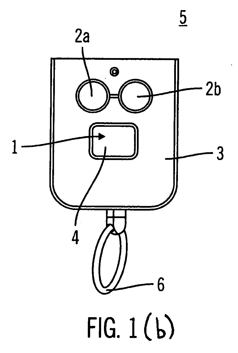
[0025] In one embodiment, the controller device is a hand-held device separate from the therapy / diagnostic device, such as an infusion device, that allows the user to communicate with the therapy / diagnostic device without actually handling the device. Other examples of therapy / diagnostic devices include electronic therapy devices and devices that receive diagnostic information from cardiac and other sensors. As illustrated in FIG. 1(b), the controller device 5 includes a housing 3 adapted to be carried by the user and a communication system (not shown) contained in the housing 3 for transmitting a communication or command from the user to the in...


PUM


Abstract

A powering subassembly for a portable electronic device includes a main battery, a converter, a backup battery, and a controller. The main battery provides a main voltage and the backup battery can provide a backup voltage. The converter receives the main voltage and increases the main voltage to at least one operating voltage. The controller receives the operating voltage from the converter, monitors the voltage of the main battery, and compares the monitored main battery voltage to a main battery low voltage threshold. The controller transmits a disconnect signal to decouple the main battery from the converter if the monitored voltage from the main battery is less than the main battery low voltage threshold. The controller transmits a connection signal to couple the backup battery to the converter if the monitored voltage is less than the main battery low voltage threshold. The backup battery provides the power for a predetermined minimum amount of time.

Description

CROSS-REFERENCE TO RELATED APPLICATIONS [0001] This is a continuation-in-part of U.S. patent application Ser. No. 11 / 204,667, filed Aug. 16, 2005, Attorney Docket No. 40088-317229, and U.S. patent application Ser. No. 11 / 204,583, filed Aug. 16, 2005, Attorney Docket No 40088-316766.BACKGROUND OF THE INVENTION [0002] 1. Field of the Invention [0003] The field of the invention is the providing of power for portable electronic devices, such as insulin pumps, analyte sensor devices, portable phones, personal digital assistants, etc. Specifically, the invention is directed to powering a portable electronic device for a known period of time after depletion of the main battery regardless of the type of battery that is installed in the portable electronic device. [0004] 2. Description of Related Art [0005] Most portable electronic devices are powered by either an alkaline battery, a lithium-ion battery, or a rechargeable battery. FIG. 1(a) illustrates a voltage level over time provided by d...

Claims


Application Information

Patent Timeline
IPC IPC(8): H02J9/00H02J7/00
CPCA61B5/14532Y10T307/615A61M5/1723A61M2205/3553A61M2205/3561A61M2205/3576A61M2205/3584A61M2205/3592A61M2205/8206A61M2230/201G06F1/30H02J7/0054H02J9/061A61M2205/581A61M2205/80A61M2209/01Y10T307/625A61M5/14244H02J7/342H02J2310/23
Inventor SPURLIN, JONGABLENZ, JOHNMEHTA, KAEZAD J.
Owner MEDTRONIC MIMIMED INC
Why Eureka
Try Eureka