Clock-signal adjusting method and device

a clock signal and clocksignal technology, applied in the direction of digital transmission, pulse automatic control, angle demodulation by phase difference detection, etc., can solve the problem of data lockout problem resulting from significant frequency difference, data rdata's frequency difference would be inevitable or unpredictable, etc. problem, to achieve the effect of solving the data lockout problem, and the frequency difference cannot be significan

Active Publication Date: 2007-02-22
VIA TECH INC
View PDF12 Cites 49 Cited by
  • Summary
  • Abstract
  • Description
  • Claims
  • Application Information

AI Technical Summary

Benefits of technology

[0006] Another embodiment of a clock-signal adjusting device for adjusting a frequency of a clock signal according to a frequency of an input data. In the clock-adjusting device, a first oversampling circuit is used for receiving and sampling the input data with a sampling frequency m times of the frequency of the clock signal to obtain a first data transition waveform indicating a first data transition timing distribution. A first flip-

Problems solved by technology

However, the differentiation of the frequencies of the data Rdata and the reference clock signal would be inevitable or unpredictable if different clock sources are used in respective interfaces or low frequency power/ground noises occur between interfaces.
If the frequency difference is beyon

Method used


Image

  • Clock-signal adjusting method and device
  • Clock-signal adjusting method and device
  • Clock-signal adjusting method and device

Examples


Embodiment Construction

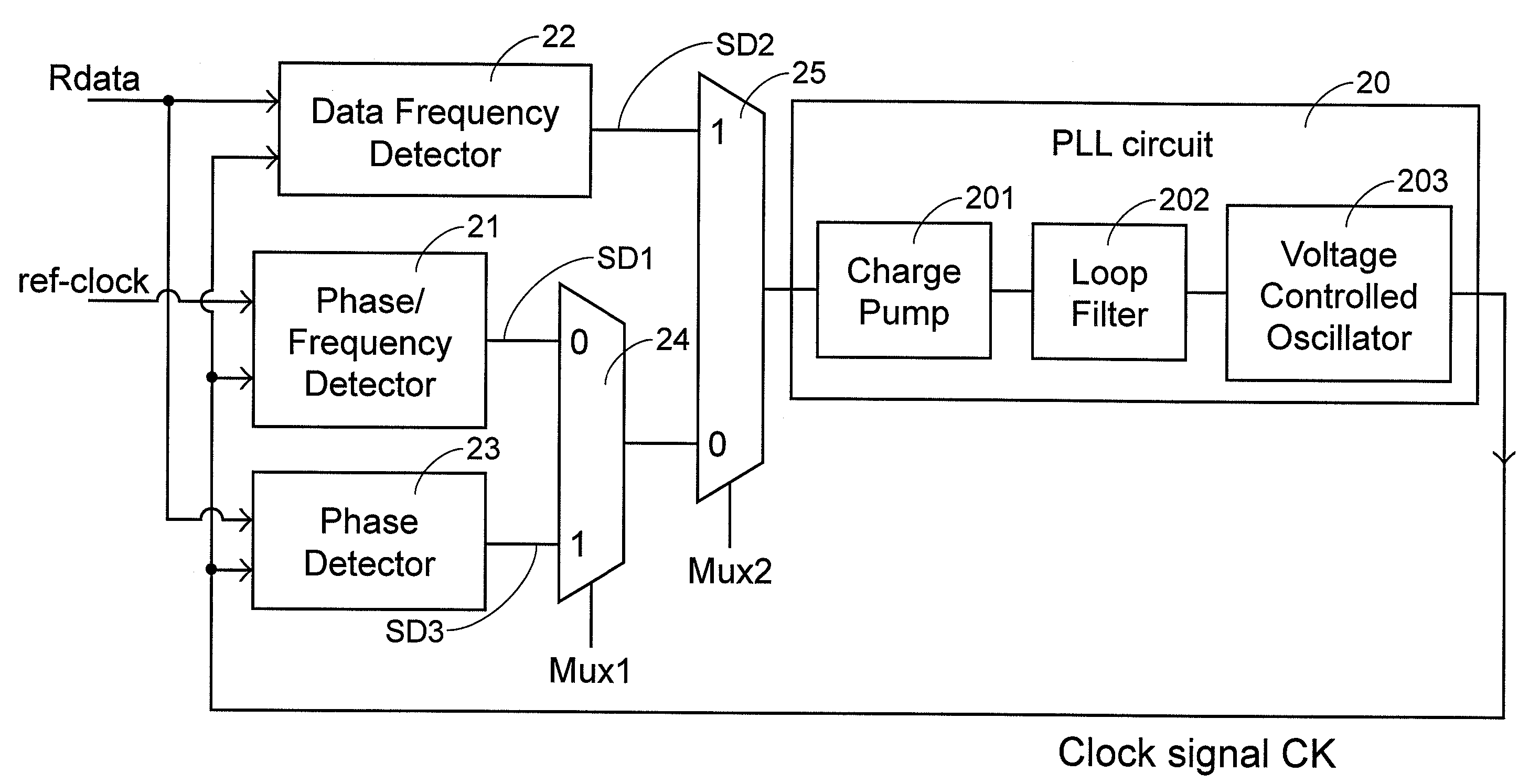
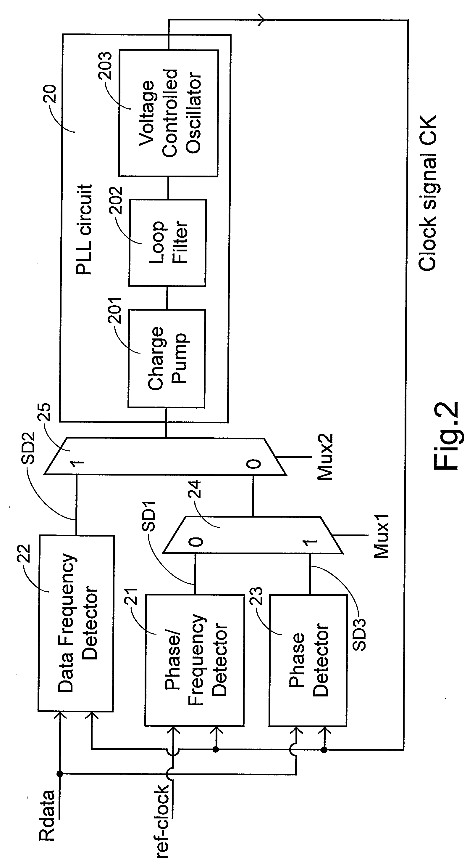
[0017] A clock-signal adjusting device according to an embodiment of the invention includes a PLL circuit 20, a phase / frequency detector 21, a data frequency detector 22, a phase detector 23, a first multiplexer 24 and a second multiplexer 25, as illustrated in FIG. 2.

[0018] For adjusting both the frequency and phase of a clock signal Ck generated by the PLL circuit 20, a series of mode transitions are involved. First of all, the system enters a first mode. In the first mode, a first adjusting signal SD1 is generated by the phase / frequency detector 21 according to the frequency difference between a local reference clock ref-clock and the clock signal Ck. The frequency of the clock signal Ck less than that of the local reference clock ref-clock is increased in response to the first adjusting signal SD1, while the frequency of the clock signal Ck greater than that of the local reference clock is decreased. By repetitive feedback and adjustment of the clock signal Ck, the frequency of...


PUM


Abstract

A clock-signal adjusting method and device is used for adjusting a frequency of a clock signal according to a frequency of an input data. The input data is sampled with a sampling frequency m times of the clock frequency to obtain a data transition waveform indicating data transition timing distribution. A unitary bit time of the input data is divided into m zones. A frequency relationship between the clock signal and the input data is determined according to a shift of the data transition waveform relative to the zones. The frequency of the clock signal is adjusted according to the frequency relationship.

Description

CROSS REFERENCE TO RELATED PATENT APPLICATION [0001] This patent application claims the benefit of U.S. provisional patent application No. 60 / 709,932, filed Aug. 19, 2005.FIELD OF THE INVENTION [0002] The present invention relates to clock-signal adjusting method and device, and more particularly to clock-signal adjusting method and device for adjusting a local reference clock according to a serial input data. BACKGROUND OF THE INVENTION [0003] The implementation of CDR (Clock Data Recovery) is a key to high speed I / O interfaces such as high speed asynchronous serial buses. FIG. 1 is a functional block diagram illustrating a portion of a Phase Locked Loop (PLL) based CDR circuit. The circuit shown in FIG. 1 includes a phase / frequency detector 11 which, in a frequency mode, outputs an up / down pulse signal according to the phase / frequency difference between a local reference clock ref-clock and a clock signal Ck generated by a voltage controlled oscillator (VCO) 16. When the frequency...

Claims


Application Information

Patent Timeline
IPC IPC(8): H03D3/24
CPCH03L7/087H03L7/091H03L7/113H03L7/14H04L7/033
Inventor CHANG, CHI
Owner VIA TECH INC
Why Eureka
Try Eureka