Automatic balancing system and method for a tomography device

a tomography device and automatic balance technology, applied in the field of imaging tomography equipment, can solve the problems of series of unwanted events, excessive bearing wear and interference, and unwanted noise development, and achieve the effect of improving the quality of imaging

Inactive Publication Date: 2007-02-22
SIEMENS AG
View PDF13 Cites 29 Cited by
  • Summary
  • Abstract
  • Description
  • Claims
  • Application Information

AI Technical Summary

Benefits of technology

[0018] An object of the present invention is based on the object to specify an imaging tomography apparatus and a method for “balancing” a tomography apparatus with which the quality of the imaging can be improved.

Problems solved by technology

In tomography apparatuses with a rapidly-rotating measurement system, existing imbalances or imbalances occurring in the course of the operation lead to a series of unwanted events.
These range from unwanted noise development to excessive bearing wear and interferences in the imaging.
Due to the limited range of electromagnets of any kind, this compensation device has the disadvantage that it is only applicable given a vertical rotation axis, thus given an annular channel situated horizontally.
Moreover, the strength or mass of the imbalance to be compensated is limited at the upper end, dependent the limited attractive force of the magnets and their limited capability to hold the attracted fluid in the subsequent operating state.
Moreover, for many applications the introduction of a fluid that remains in the fluid state in the rotating operating mode does not fulfill requirements for operating safety, for example with regard to residual vibrations or agitations or even leakage given a malfunction.
Under the influence of the imbalance, the compensation masses distribute unevenly and tend to compensate the vibrations and the imbalance.
The device described in SU 1771893 also has the disadvantage that only slight imbalances, for example caused by a missing tooth on the milling cutter, can be corrected.

Method used


Image

  • Automatic balancing system and method for a tomography device
  • Automatic balancing system and method for a tomography device
  • Automatic balancing system and method for a tomography device

Examples


Embodiment Construction

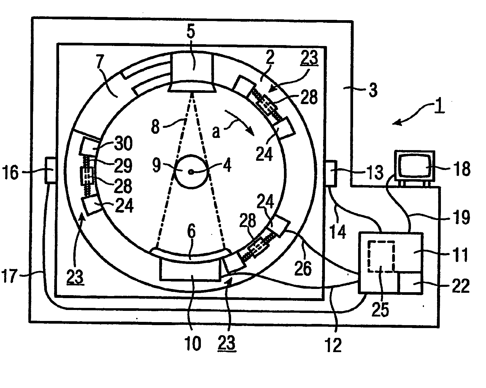
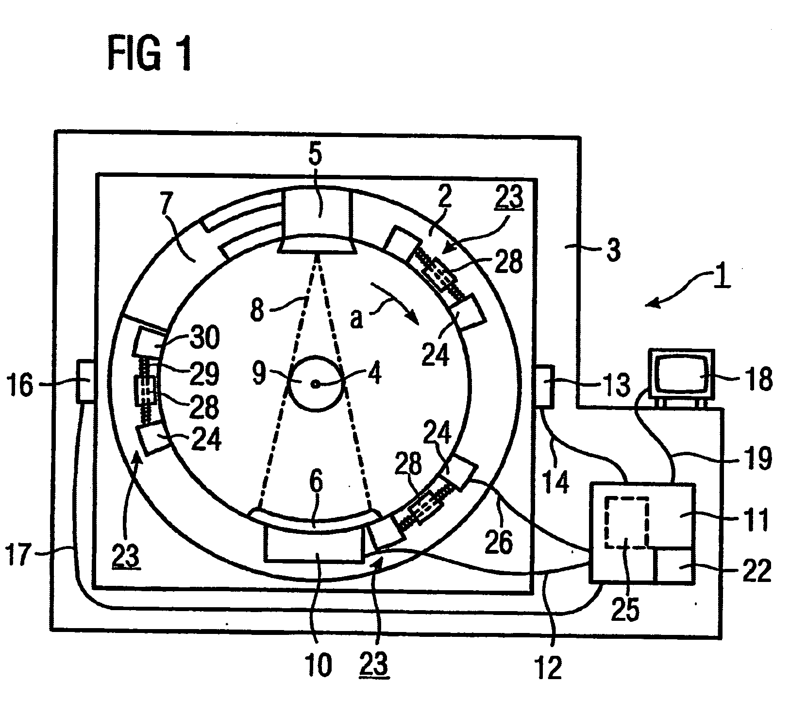
[0075]FIG. 1 shows an x-ray computed tomography apparatus 1, as an example of a rotatable device. The tomography apparatus 1 has a measurement system 2 as a rotatable part of the gantry, The measurement system 2 is capable of rotating in a stationary housing 3 around a virtual horizontal rotation axis 4 perpendicular to the drawing plane. A number of components are arranged on the measurement system 2, namely an x-ray source 5, an x-ray radiation detector 6 opposite the x-ray source 5 and a cooling device 7 (only schematically indicated) for dissipation of heat that is generated by an x-ray tube of the x-ray source 5 in the operation of the computer tomography apparatus 1. In the operation of the computer tomography apparatus 1, the measurement system 2 rotates around the rotation axis 4, whereby a fan-shaped x-ray beam 8 emanating from the x-ray source 5 penetrates a measurement field 9 at various projection angles and strikes the radiation detector 6. The resulting output signals ...


PUM

PropertyMeasurementUnit
sizeaaaaaaaaaa
sizeaaaaaaaaaa
imaging tomographyaaaaaaaaaa

Abstract

The invention relates to a tomography device (1), especially an X-ray computer tomography device or ultrasound tomography device, comprising a balancing device (23; 45) for reducing an imbalance (61) that was determined by means of the measuring system (2) rotating about an axis of rotation (4). The balancing device (23; 45) comprising means mounted on the measuring system (2) for variably positioning a balancing mass and a control device (25) acting upon said means and designed in such a manner that the balancing mass, controlled by the control device (25), can be positioned in a location appropriate to reduce the imbalance (61). The balancing mass can be configured as a liquid (F) that is positioned in a liquid-tight channel. The invention also relates to a balancing method according to which a mass (m) of a liquid quantity balancing the imbalance (61) is determined and a magneto- and/or electro-rheological liquid (F) is introduced into an annular channel (31; 71; 81, 83, 85) in such a quantity that for the subsequent operation a quantity of liquid (F) dependent on the determined mass (m) is present in the annular channel (31; 71 81, 83, 85).

Description

BACKGROUND OF THE INVENTION [0001] 1. Field of the Invention [0002] The present invention lies in the field of imaging tomography apparatuses, in particular in the field of medical technology. [0003] The invention is concerned with an imaging tomography apparatus, in particular an x-ray computer tomography apparatus or ultrasound tomography apparatus, with a measurement system that can rotate around a rotation axis and with a compensation device to minimize an imbalance detected in the measurement system. [0004] The invention moreover concerns a method for minimization of an imbalance at a measurement system of a tomography apparatus, which measurement system can rotate around a rotation axis, of the type having an annular channel centered on the rotation axis and that can be filled with fluid. [0005] 2. Description of the Prior Art [0006] In tomography apparatuses with a rapidly-rotating measurement system, existing imbalances or imbalances occurring in the course of the operation ...

Claims


Application Information

Patent Timeline
Patent Type & Authority Applications(United States)
IPC IPC(8): H05G1/60A61B6/00G01N23/00G21K1/12A61B6/03F16F15/36G01M1/32
CPCA61B6/035A61B6/447G01M1/323F16F15/366F16F2224/045A61B6/4488
Inventor HOHEISEL, MARTINMULLER, HANS-JURGENMULLER, NORBERT
Owner SIEMENS AG
Why Eureka
Try Eureka