Earphone and speaker module for earphone

Inactive Publication Date: 2007-02-22
COTRON
View PDF2 Cites 10 Cited by
  • Summary
  • Abstract
  • Description
  • Claims
  • Application Information

AI Technical Summary

Benefits of technology

[0009] Accordingly, at least one objective of the present invention is to provide an

Problems solved by technology

However, the aforementioned method of adjusting the sound quality of the earphone demands some trial-and-error and several design improvements before an earphone with optimal sound quality is produced.
As a result, the cost of designing the earphone is increased.
Moreover, the size and location of the o

Method used


Image

  • Earphone and speaker module for earphone
  • Earphone and speaker module for earphone
  • Earphone and speaker module for earphone

Examples


Embodiment Construction

[0025] Reference will now be made in detail to the present preferred embodiments of the invention, examples of which are illustrated in the accompanying drawings. Wherever possible, the same reference numbers are used in the drawings and the description to refer to the same or like parts.

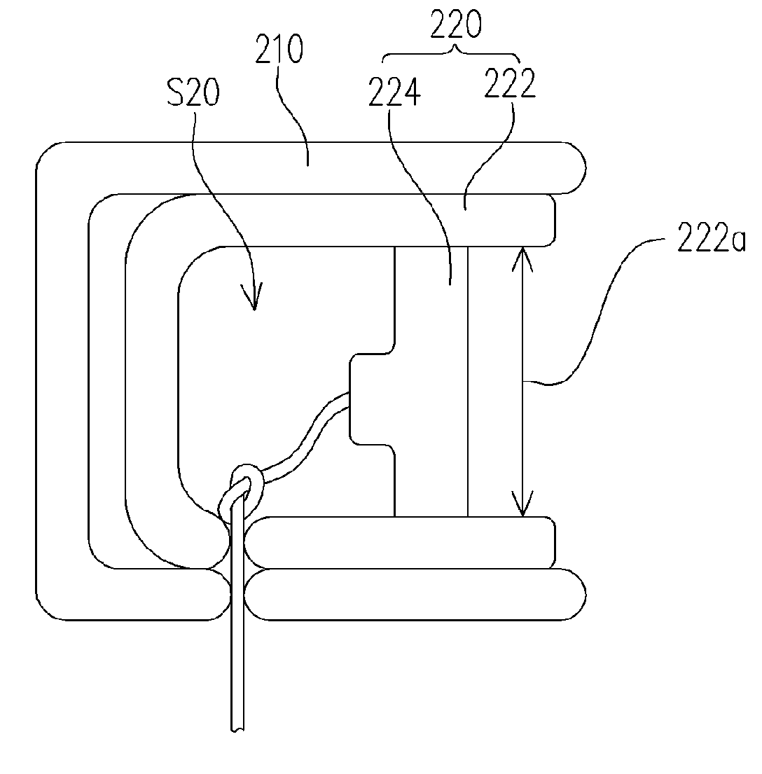
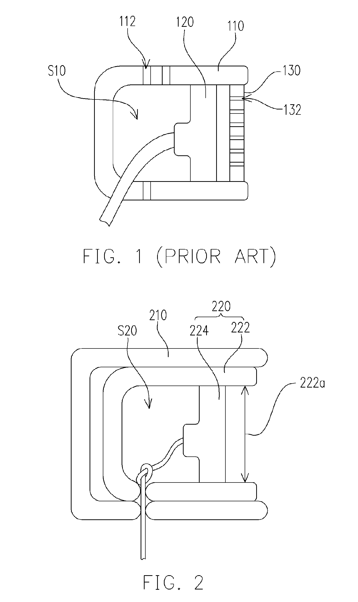
[0026]FIG. 2 is a schematic cross-sectional view of an earphone according to a first embodiment of the present invention. As shown in FIG. 2, the earphone in the present embodiment comprises an earphone housing 210 and a speaker module 220. The speaker module 220 is disposed inside the earphone housing 210. The speaker module 220 further comprises a speaker housing 222 and a speaker unit 224. The speaker housing 222 constitutes a resonant chamber S20 and the speaker unit 224 is disposed inside the resonant chamber S20. The speaker unit 224 comprises a speaker vibration system and a magneto-electric circuit, for example. The speaker vibration system can be a vibration film on an electric coil. Obvio...


PUM


Abstract

An earphone comprising an earphone housing and a speaker module is provided. The speaker module is disposed inside the earphone housing. The speaker module further comprises a speaker housing and a speaker unit. The speaker housing has a sound emission opening. In addition, the speaker housing constitutes a resonant chamber. The speaker unit is disposed inside the resonant chamber.

Description

CROSS-REFERENCE TO RELATED APPLICATION [0001] This application claims the priority benefit of Taiwan application serial no. 94127989, filed on Aug. 17, 2005. All disclosure of the Taiwan application is incorporated herein by reference. BACKGROUND OF THE INVENTION [0002] 1. Field of the Invention [0003] The present invention relates to an electronic product. More particularly, the present invention relates to an earphone and a speaker module for an earphone. [0004] 2. Description of the Related Art [0005] With the continuous advance in technologies, lighter and smaller electronic products are produced. As electronic products gets smaller and lighter, more and more people are carrying these miniaturized products such as radio or portable music player around. In addition, the popularization of personal digital products such as MP3 players, mobile phones, personal digital assistants (PDA) and notebook computers has rendered such equipment an indispensable part of our daily life. Further...

Claims


Application Information

Patent Timeline
IPC IPC(8): H04R25/00
CPCH04R1/1016H04R1/025
Inventor YANG, BILL
Owner COTRON
Why Eureka
Try Eureka